Download
1 / 30
300 likes | 517 Views
Architectural Requirements Phase. See Sommerville Chapters 11, 12, 13, 14, 18.2. Architectural Requirements Phase. S oftware requirements concerned construction of a logical model Architectural requirements concern construction of a physical model

E N D
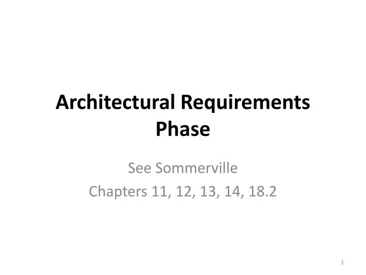
Architectural RequirementsPhase See Sommerville Chapters 11, 12, 13, 14, 18.2
Architectural Requirements Phase • Software requirements concerned construction of a logical model • Architectural requirements concern construction of a physical model Architecture ”bible” : M. Shaw & D. Garlan, Software Architecture, Prentice Hall, 1996.
Architectural Design Concerns • physical system partitioning • allocation of tasks to components • high cohesion and low coupling = good / robust • low cohesion and high coupling = bad / fragile • high cohesion (high element dependence inside components) • low coupling (low component interdependence, so design is robust against change) • component interface design • component reuse • choice of architecture to meet performance and other non-functional requirements • problem solution by divide and conquer
Architecture Design Process Mostly, we will instantiate a well known global architecture, as well as sub-architectures and design patterns … … by top-down refinement … all the way down to unit level.
Architecture Selection Criteria • Is there a generic architecture or pattern that can be a template for the system or component? (Otherwise ad-hoc.) • How will the system be distributed across hardware to achieve performance, security, reliability etc? • Which generic architectures provide different alternatives, and what are the tradeoffs? (tradeoff analysis)
Architecture Selection (cont.) (4) How can each component be decomposed into sub-components – (divide-and-conquer, maximise reuse, cohesion vs. coupling) (5) How to implement control and co-operation (6) How to evaluate the design? (predict performance?) (7) How to document the design (static, dynamic, UML?) especially component interfaces so that coders can work to an interface specification.
System Models Documentation depends on which kinds of system models we use: • Static structural model (class or package diagram) • Dynamic process model – run time behavior (sequence diagram, statechart) • Interface model (class diagram, OCL, JML) • Relationship model (data flow diagram) • Distribution model – across hardware (package diagram) • Testing model – define integration tests (JUnit, JBehave, TTCN)
Architecture 1: Client-Server * * Server service1() service2() … serviceN() Client requester provider Request for service using RPC or CORBA, Java RMI, HTTP, etc.
Architecture2: Three-TierDatabaseArchitecture 3. Interface layer 2. Application logic layer 1. Storage layer Interface layer: objects dealing with user, windows, forms, Web pages, etc Application logic layer: control and entity objects for processing, Rule checking and notification Storage layer: implements storage, retrieval and query of persistent objects
Architecture3: Four-TierDatabaseArchitecture Interface layer of 3-tiered 4. Presentation Client 3. Presentation Server 2. Application logic layer 1. Storage layer Presentation Client sits on user machine. Presentation Server sits on server machine Different kinds of clients and servers possible Compare with MVC!
Possible Instantiation of 4 tiers Interface layer 4. WebBrowser 3. Server Side Form 2. DB Connection 1. SQL Query
Architecture 4: Layered Subsystems hierarchically organized, each layer (1) depending only on layer below, (2) supplying services to layers above (iterated client-server?)
Possible Instantiation ISO/OSI 7 –layer communication hierarchy 7. Application (mail, telnet, ftp ) 6. Presentation (XDR) 5. Session (RPC) 4. Transport (TCP, UDP) 3. Network (IP) 2. Data Link (Ethernet) Hardware level 1. Physical (thinnet, thicknet, UTP)
Architecture 5: Data Centered Centralisearound a large data collection, aka repository App3 App1 App2
Architecture 6 : Independent components Executing in parallel, with communication, aka object-oriented architectures. e.g. simple OOP, peer to peer (2-way client- server)
Architecture 7: Model-View-Controller (MVC) An architecturalmodel that solvesmany userinterface (UI) problems, e.g. • shared data, • multiple users, • different views of the same data, • updating information across all users, • changes to underlying data, • changes to representation, • changing UI technology.
MyView viewData initialize() displayData() update() depends on Model * 1 coreData setOfObservers attach(Observer) detach(Observer) notify() getData() modifyData() 1 1 updates MyController updates viewData initialize() changeData() update() * 1
Architecture 8: Data Flow Data flows between static functional elements which transform it, aka pipeline architecture e.g. compiler C code assembler Machine code parse tree Parse Translate Link & Assemble procedure calls assembler Library
Design Patterns • Are the answer to a question that commonly arises “How can I … ?” • Patterns record successful solutions in software development for sharing between projects. • Gang of Four (GoF) Gamma, Helm, Johnson, Vlissides, - founders of movement. • Gamma et al, Design Patterns: Elements of Reusable Object-Oriented Software, Addison Wesley, 1995. • Literally thousands of patterns … !
Typesof Pattern Basically 3 types of pattern … • Creational: address problems of creating an object in a flexible way. Separate creation, from operation/use. • Structural: address problems of using O-O constructs like inheritance to organize classes and objects • Behavioral: address problems of assigning responsibilities to classes. Suggest both static relationships and patterns of communication
Example Pattern:Mediator(Behavioral) Problem: How can we deal with two or more classes which sometimes interact, but can also be used separately? Solution: Mediator promotes loose coupling by keeping objects from referring to one another explicitly. Put each interaction between objects in a separate (Mediator) class. This class should have references to the objects.
A pattern for two objects which exist independently but have some coupling. This coupling is placed in its own class. • Used by e.g. ActionListener in Java which couples together two graphical objects, e.g. window & button. • Colleagues send and receive requests from a Mediator object. The mediator implements the cooperative behavior by routing requests between appropriate colleagues.
Mediator Structure mediator 1 Mediator Colleague * ConcreteMediator Concrete Colleague1 Concrete Colleague2 *
Comments • Façade, unlike Mediator, abstracts a subsystem of objects to provide a convenient interface. Unidirectional. Façade objects make requests of the subsystem, but not vice-versa. • Mediator enables cooperative behaviour, that colleagues don’t or can’t provide. Multidirectional.
PSS-05 ARD Template Sections 1 and 2 are similar to SRD template. 3. System Context. Gives a detailed description of the system context, with relevant diagrams. Defines the external interfaces of the product under development for these other systems 3.n. External interface definition. Provides an interface definition to each separate external component type or physical component.
4 System Design. Provides an overview of the design techniques used, especially any in-house or non-standard notations, project specific methods, or non-standard interpretation of standard languages/methods such as UML/Waterfall. 4.1 Design method. Describes and references the design method. “Why we did what we did.” 4.2 Decomposition description. Gives the top level view of the systems design, preferably with diagrams. Shows the major components which will be described in detail in Section 5. Identifies control and data flow between components.
5 Component Description. Gives detailed component information according to a fixed template. Components may be top level components, identified in Section 4.2, or subcomponents of these. Preferably use a component identification scheme which is easy to read/follow/remember. 5.n [Component identifier] Fill in name here. 5.n.1 Type. Could be a module, an input/output/temporary file, a program, a class, a script, a web page, etc. 5.n.2 Purpose. Describe the purpose of the component, and relate this to a numbered software requirement in the SRD. 5.n.3 Function. Describe the functionality of the component, including its interface properties (call and return types) and logical behaviour. 5.n.4 Subordinates. List the immediate subcomponents of the component, using defined component identifiers.
5.n.5 Dependencies. Describe the logical preconditions for using this component, e.g. files and/or objects which must exist. 5.n.6 Interfaces. Define the control and data flow to and from the object. Gives a detailed picture of its context in the overall system architecture. 5.n.7 Resources. List any resources required by the component, such as external components external subsystems, hardware, etc. 5.n.8 References. reference any documents needed to understand the component. 5.n.9 Processing. Describe the control and data flow betwen immediate subcomponents of this component. If the component has no immediate subcomponents (i.e. it is fully decomposed) then outline the method of processing used by the component to perform its task (e.g. with pseudo-code, state diagrams, etc). 5.n.10 Data. Describe in detail (where possible) the local data values and data structures belonging to (local in scope) this component. Otherwise give an outline description.
6 Feasibility and Resource Estimates. Summarize the conclusions of a feasibility study around the architectural model. Prioritizeall components using a priority model (e.g. economy, standard, deluxe versions). Identify and describe all future project tasks. Identify task dependencies in terms of commencement and completion, preferably with a task flow chart. Estimate the effort required for each project task. Produce a task allocation plan and schedule for each project staff member for the remainder of the project. This information should preferably be presented in a table.
Identify possible risks going forward, and for each risk, give a risk management proposal. Estimate the overall schedule for making a detailed design, coding this design, testing and delivering the final product and documentation according to the project deadlines. Identify the critical path in the project, and analyze possible project slippage along this path. 7 Software Requirements vs Components Traceability Matrix. Gives a table cross referencing architectural components (based on defined component identifers).