Download
1 / 25
250 likes | 254 Views
Learn about the MSP430 cross-assembler and how it translates assembly source code into machine code for the MSP430 microcontroller.

E N D
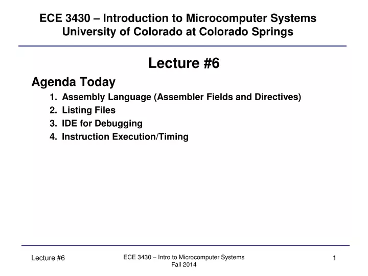
ECE 3430 – Introduction to Microcomputer SystemsUniversity of Colorado at Colorado Springs Lecture #6 Agenda Today • Assembly Language (Assembler Fields and Directives) • Listing Files • IDE for Debugging • Instruction Execution/Timing ECE 3430 – Intro to Microcomputer Systems Fall 2014
Assembler Fields MSP430 Cross-Assembler • The MSP430 cross-assembler takes assembly source code and translates it to machine code that the MSP430 understands. The assembler is run on a standard PC. • The cross-assembler reads the text file (*.s43 file) and decodes the text depending on which column the text is in. There are four columns that are called assembler fields: 1) Label 2) Opcode 3) Operand 4) Comment ECE 3430 – Intro to Microcomputer Systems Fall 2014
Assembler Fields Label Field • Text that is not proceeded by a white space character (i.e., the first character of a line) is treated as a label. A label is a piece of text that gets assigned the memory address of where it is located in the file. • This makes tracking memory addresses easier: Ex) FC00h Main mov.w Main,R5 FC04h Main2 mov.w &Main2,R5 FC08h mov.w #Main,R5… In the above: • “Main” is assigned the value of FC00h, “Main2” is assigned the value of FC04h. • FC00h is substituted everywhere in the code that “Main” is typed and FC04h for “Main2”. • mov.w Main,R5 Symbolic or PC-relative • Same as mov.w FC00h,R5 mov.w -2(PC),R5 • mov.w &Main2,R5 Absolute or SR-relative (constant 0 relative) • Same as mov.w &FC04h,R5 mov.w FC04h(SR),R5 • mov.w #Main,R5 Immediate Addressing • Same as mov.w #FC00h,R5 mov.w @PC+,R5 Labels are commonly used: • To address variables allocated in RAM. • To provide a target address for jump instructions (discussed later). ECE 3430 – Intro to Microcomputer Systems Fall 2014
Assembler Fields Opcode Field • Text that is proceeded by 1 group of white space (i.e., a tab) is treated as an opcode. • Opcodes are specified to the MSP430 assembler via mnemonics. Only instruction mnemonics (or assembler directives) can be used in this field. If the assembler does not recognize the mnemonic (it doesn’t exist), it will present an error. • Example mnemonics: mov, jnz, bis • See MSP430 Instruction Set Summary for a list of all mnemonics. Operand Field • Text that follows a mnemonic is treated as an operand (3rd column) mov.w #0280h,SP Operands ECE 3430 – Intro to Microcomputer Systems Fall 2014
Assembler Fields Comment Field • Comments are used to make notes about what you are doing. You must comment your code in the lab if you expect the lab instructors to help you. • There are a couple of ways to enter a comment: • The fourth column of the text file is treated as a comment field. Place a semicolon (;) in front of the comment to make it readable and ensure the assembler treats what follows it as a comment. The assembler disregards comments because they are only for the programmer’s use and are no use to the assembler. Ex) mov.b #FFh,R4 ; this instruction loads FFh into R4 and zeroes ; out the upper 8 bits • Placing a semicolon (;) as the first character of a line. The entire line is treated as a comment. Ex) ; start of code ; Main mov.b #FFh,R4 ; this line will be skipped by the assembler ECE 3430 – Intro to Microcomputer Systems Fall 2014
Assembler Directives Source Code – When you write a program, you will include additional information besides just instructions. Sometimes the assembler needs more information: 1) Where in memory should the program be loaded? 2) Memory allocation for program data 3) Variable names 4) Global constants 5) Et cetera Directives - We accomplish the above using assembler directives. The assembler directives are specific to the cross- assembler. The assembler recognizes directives as keywords and knows what to do. Directives are not MSP430 instructions! ECE 3430 – Intro to Microcomputer Systems Fall 2014
Assembler Directives Two-Pass Assembler - A cross-assembler reads in the source file in at least two passes (scans the input file twice). Depending on how an assembler or a compiler is written, it may do more than two passes. The two-passes might be as follows: 1st Pass: - Assembler directives concerning program location are decoded and memory locations are setup. - Labels, constants, and variable names are resolved and stored in memory.2nd Pass - Opcode / operands are decoded and given a memory location of where they are to be downloaded. - Labels, constants, and variable names are substituted in. ECE 3430 – Intro to Microcomputer Systems Fall 2014
Assembler Directives (Absolute) ORG - This tells the assembler where to insert the program code. Any instructions that follow this directive will be inserted sequentially into memory.AddressMachine CodeEx) ORG 0xE000 E000h <instruction – lower 8> mov.b #FFh,R4 assemble E001h <instruction – upper 8> mov.w #FFFh,R5 E002h FFh E003h 00h E004h <instruction – lower 8> E005h <instruction – upper 8> E006h FFh E007h 0Fh Ex) ORG 0x0200 RAM: … ; RAM is a label for address location 0x0200ORG 0xF000 ; we now move to 0xF000 to insert the following mov.w RAM,R4 ; R4 = M(0200h), RAM = $0200 ECE 3430 – Intro to Microcomputer Systems Fall 2014
Assembler Directives END - This tells the assembler that your program ends hereEx) ORG E000h ; start code at 0xE000 Main mov.b #FFh,R4 ; load R4 with FFh mov.b R4,0h ; store FFh to memory location 0x0 jmp Main ; repeat the above two instructions forever END ; this is the end of the code NOTE: The END directive does not have anything to do with program flow, it only tells the assembler when you are done writing your code. This directive is not required. Once the assembler hits the END directive, it quits processing your input file. ECE 3430 – Intro to Microcomputer Systems Fall 2014
Assembler Directives DS - Define Storage. This reserves a block of memory for use as program data and variables. It does not initialize the memory locations.Ex) ORG 0x0200 myVar1 DS 2 ; reserve a 16-bit variable myVar2 DS 1 ; reserve an 8-bit variable ORG 0xE000 ; start code at 0xE000 mov.b myVar2,R4 ; put contents of 0x0202 into R4 … AddressMachine Code 0200h ??h -> myVar1 lives at 0x0200 0202h ??h -> myVar2 lives at 0x0202 … E000h <instruction – upper 8> E001h <instruction – lower 8> E002h <offset from E003h to get to 0202h> NOTE: An unknown value is loaded into R4 in the above example! ECE 3430 – Intro to Microcomputer Systems Fall 2014
Assembler Directives DB – Declare Byte. This reserves a byte of memory and initializes the byte to a certain value.Ex) ORG 0200h ; start code at 0x0200 myVar1 DB 12h ; reserve and insert 0x12 into 0x0200 myVar2 DB 11h,22h ; reserve the next two bytes and insert… ORG E000h mov.b myVar1,R4 mov.w myVar2,R5 mov.w #myVar2,R6 … AddressMachine Code 0200h 12h variable myVar1 lives here 0201h 11h variable myVar2 lives here 0202h 22h After the last mov instruction, R4 = 12h, R5 = 2211h, and R6 = 0201h ECE 3430 – Intro to Microcomputer Systems Fall 2014
Assembler Directives DW - Declare Word. Same as DB but will allocate and initialize 2 bytes at a time.Ex) ORG E000h ; start code at E000h myNum1 DW 1234h ; reserve and insert 1234h myNum2 DW 11h ; reserve and insert 0011h AddressMachine Code E000h 34h variable myNum1 lives here E001h 12h E002h 11h variable myNum2 lives here E003h 00h ECE 3430 – Intro to Microcomputer Systems Fall 2014
Assembler Directives DB - Can also be used for ASCII strings. Will reserve memory and insert the ASCII code for the text given.Ex) ORG 0E000h ; start code at E000h myAlpha: DB ‘DEF’ ; reserve and insert ASCII code <or> DB “DEF” ; reserve and insert ASCII code + terminator AddressMachine Code E000h 44h -> Labeled “myAlpha” E001h 45h -> Labeled “myAlpha + 1” E002h 46h -> Labeled “myAlpha + 2” E003h ??h <or> 00h NOTE: The ASCII code for : D = 44h E = 45h F = 46h (see ASCII table) ECE 3430 – Intro to Microcomputer Systems Fall 2014
Assembler Directives EQU - This equates one value or label with another value or label. Establishes an alias.Ex) myVar1 EQU 0FEh myVar2 EQU 0ABCDh myVar3 EQU myVar1 ORG 0E000h ; start code at 0xE000 mov.b #myVar1,R4 ; R4 = 0xFE mov.b myVar2,R5 ; R5 = 00h:M(0xABCD) mov.w myVar3,R5 ; R5 = M(0x00FF):M(0x00FE) … NOTE: The assembler will insert 0xFE for myVar1, 0xABCD for myVar2, and 0xFE for myVar3. ECE 3430 – Intro to Microcomputer Systems Fall 2014
Assembler Directives (Relocatable) RSEG - Relocatable Segment. Instead of ORG or ASEG (absolute segment). Usage: RSEG CODE marks the beginning of code segment (Flash) RSEG DATA marks the beginning of data segment (RAM) RSEG RESET points to the reset vector (non-volatile) NOTE: A complete list of assembler directives can be found in the assembler reference guide under the Help menu in EW430. ECE 3430 – Intro to Microcomputer Systems Fall 2014
Lab Setup Putting it all together may look like this… ; This is a program that will load the contents of memory location ; 0x0201 and store the contents back to 0x0200 continuously. ; Matt Laubhan ; ECE 3430 ; Date: 9/18/2014 RAM EQU 0x0200 ; setting up label for address 0x0200 FLASH EQU 0xC000 ; setting up label for address 0xC000 RSEG DATA ; or ORG RAM myVar1 DS 1 ; setting up variable called “myVar1” myVar2 DB 00h ; setting up variable called “myVar2” and init to zero myText DB ‘Hi’ ; setting up variable called “myText” and init to ASCII string RSEG CODE ; or ORG FLASH MAIN mov.b myVar2,R4 ; R4 M(myVar2) = M(0x0201) mov.b R4,myVar1 ; M(myVar1) = M(0x0200) R4 jmp MAIN ; branch always back to “MAIN” (program counter trapped) END ; the code is done here ECE 3430 – Intro to Microcomputer Systems Fall 2014
Listing Files Listing files are generally optional output from assembler, sometimes useful in debugging. With a rich debugging environment, directly looking at listing files is not always required. In any listing file, multiple columns of data are appended to the left of the original assembly source code and may contain: • Line number • Address in memory • Opcode • Operands • Cycle count for instruction Format and amount of output data depend on the tools. ECE 3430 – Intro to Microcomputer Systems Fall 2014
IDE for Debugging The IDE can host a debugging session against simulated or real hardware. During debugging, the debugger can provide the following: • Source window code stepping (assembly or higher-level). • Reverse assembly if debugging higher-level code. • Memory contents (RAM and Flash). • CPU register contents. • Stack contents Function/Subroutine call-stack. • Use of breakpoints. • Code re-direction (skipping/repeating lines of code). • … ECE 3430 – Intro to Microcomputer Systems Fall 2014
Instruction Execution/Timing Instruction Cycles A single MSP430 instruction will involve 1 or more read cycles and 0 or more write cycles. During every cycle (be it read or write) additional data may be moving through the ALU. No cycles are performed when there is no activity on the MAB/MDB in this architecture. Read Cycle: Process of accessing memory to retrieve data or program instructions. The data goes from memory to registers. Write Cycle: Process of storing a value to memory. The data goes from registers to memory. All instructions will at least perform one 16-bit read to retrieve the instruction code for the instruction to be executed. The PC will be pointing to where the instruction is located. ECE 3430 – Intro to Microcomputer Systems Fall 2014
Instruction Execution/Timing • Generally speaking, instructions take 1 cycle per word of memory accessed (this is due to the 16-bit data bus and 16-bit CPU). • 1 read cycle for instruction code + 1 read cycle per source offset word (if indexed) + 1 read cycle for memory source (if not register direct) + 2 cycles for memory destination (if not register direct) • In two-operand instructions, memory destinations may have a destination offset word too (if indexed) that costs 1 more read cycle. • The two or three cycles for the memory destination is composed of a 1 or 2 read cycles and a single write cycle. The write cycle is a write-back. • During register indirect autoincrement, the autoincrement occurs during the access of the register (no additional cycles). ECE 3430 – Intro to Microcomputer Systems Fall 2014
Instruction Execution/Timing • Immediate constants -1,0,1,2,4,8 use the constant generators and count as register direct accesses (no extra cycles). • Program counter (PC) always increments by 2 (or is set to an even address). • Non-logical and non-arithmetic instructions (that do not need to read the destination first) will still do so on the standard MSP430. • Ex) mov • This has been sped up on the MSP430X to eliminate unneeded cycles. • Exceptions (for future reference only): • Two-operand instructions which write to PC (R0) take an extra cycle. • Jumps always take 2 cycles (whether taken or not). • push, call, and reti instructions are special (see datasheet). ECE 3430 – Intro to Microcomputer Systems Fall 2014
Instruction Execution/Timing Instruction cycle during (absolute addressing): mov.w &1234h,R4 mov.w 1234h(SR),R4 • 16-bit instruction code fetch read • Fetch source offset (0x1234) read • Fetch word at offset 0x1234 read Total: 3 cycles Or mov.w R4,&1234 mov.w R4,1234h(SR) • 16-bit instruction code fetch read • Fetch destination offset (0x1234) read • Fetch word at offset 0x1234 read (not needed) • Copy contents of R4 to 0x1234 write Total: 4 cycles ECE 3430 – Intro to Microcomputer Systems Fall 2014
Instruction Execution/Timing # of Clock Cycles - In previous example, the data move operations took 4 clock cycles. These are referred to as MCLK cycles. Multiple XTAL pulses make up a single MCLK cycle. Clock Timing (based on Master Clock) - In one uC MCLK cycle, an address can be put on the address bus, decoded by memory circuitry, and the contents of that address presented back across the data bus to the uC (this is a read cycle). In one uC MCLK cycle, an address can be placed on the address bus, decoded by memory circuitry, and the new contents driven by the uC across the data bus (this is a write cycle). - See the MSP430 Instruction Timing link for more info. ECE 3430 – Intro to Microcomputer Systems Fall 2014
Instruction Execution/Timing Instruction cycle during (immediate addressing): mov.w #0F12h,R4 mov.w @PC+,R4 • 16-bit instruction code fetch read • Fetch immediate value (0x0F12) read Total: 2 cycles Instruction cycle during (indexed addressing): mov.w 4(R4),8(R5) • 16-bit instruction code fetch read • Fetch source offset (4) read • Fetch data at source EA read • Fetch destination offset (8) read • Fetch data at destination EA read (not needed) • Copy source EA word to destination EA write Total: 6 cycles EA = Effective Address ECE 3430 – Intro to Microcomputer Systems Fall 2014
Instruction Execution/Timing Instruction cycle during (symbolic addressing): mov.w 0F12h,R4 mov.w x(PC),R4 • 16-bit instruction code fetch read • Fetch source offset x read • Fetch data at source EA read Total: 3 cycles Instruction cycle during (register indirect autoincrement): mov.w @R4+,8(R5) • 16-bit instruction code fetch read • Fetch data at source EA (and increment) read • Fetch destination offset (8) read • Fetch data at destination EA read (not needed) • Copy source EA word to destination EA write Total: 5 cycles EA = Effective Address EA = Effective Address ECE 3430 – Intro to Microcomputer Systems Fall 2014