Download
1 / 65
2.05k likes | 4.57k Views
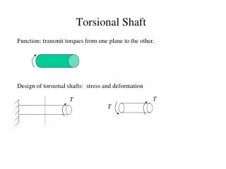
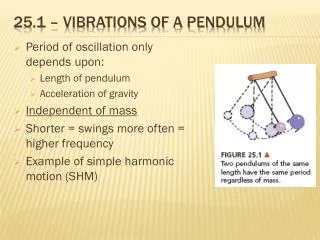
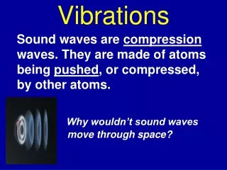
Vibrations of a rotating shaft. Torsional vibration Longitudinal vibration Transverse vibration (whirling) discussed separately. Vibrations. Periodic excitation force f = F sin t acts on the mass. F. Period T. Frequency f = 1 / T [1 / second]

E N D
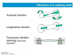
Vibrations of a rotating shaft Torsional vibration Longitudinal vibration Transverse vibration (whirling) discussedseparately
Vibrations Periodic excitation force f = F sin t acts on the mass F Period T Frequency f = 1 / T [1 / second] Natural frequency f = 2 k / m Angular velocity = 2 f [radian / second] Forcetransmitted to foundation Ftr has same frequency and same sinusoidal form as the excitation force Ftr
Dynamic magnification at the resonance Ratio of excitation force and transmitted force F / Ftr Ftr/ F F Internal damping of the spring rounds-off the resonance peak and 'softens' the phase shift 1.0 Ftr Frequency Opposite phase Same phase
Vibrations Pure sinusoidal force excites vibration of the same frequency. Magnification is smaller or larger than 1.0 depending on how close the resonance lies. Excitation Frequency Amplitude LOWBelow natural frequency RESONANCEEqual to natural frequency HIGHAbove natural frequency
Vibrations Non-sinusoidal force excites vibration of many various frequencies. Amplitude can be smaller or larger depending on the pulse form and the location of resonances. Excitation Pulse frequency Amplitude VERY LOW MEDIUM HIGH VERYHIGH
Vibrations Non-sinusoidal excitation (‘pulses’) consists of endless number of sinusoidal curves, so called harmonic components. Fourier analysis is the mathematical method to calculate components. 1/T 1/2T 1/3T 1/4T 1/5T 1/6T Period = T Frequency = 1/T 1/7T 1/8T 1/9T1/10T1/11T etc.
Torsional vibration When any harmonic component is equal to the natural vibration form, resonance occurs. The responses in resonance are typically sinusoidal. Even when basic excitation has strange pulse form. Outside resonance the vibration is not sinusoidal. If strain gauges are attached on shaft to record torque variation Typical signal in resonance is sinusoidal: Outside resonance signal is irregular, but still periodical:
Shaft vibrations - general Every system has natural vibration modes and frequencies. Periodic excitation comes from diesel engine or propeller. If excitation frequency = natural frequency, resonance exists. Responses are magnified. Free end amplitude may be 3.0 mrad (0.17 degrees), shear stress amplitude 25 MPa (25 N/mm2) Operation in resonance is avoided. Often only major resonances can be avoided and minor ones must be accepted. Sometimes stress is critically high even outside resonance. Damage is seldom shaft fracture. More often problem is wear in attached components.
Crankshaft stresses , 6-cyl. low speed engine Order 6.0 shear stress without damper Shear stress amplitude MPa Permitted 80 Order 6.0 shear stress with damper varustettuna 60 40 20 40 60 80 100 120 140 160 180 rpm Nominal speed
Crankshaft stresses, MS Dredge Queen Shear stress amplitude MPa Permitted by LR for 315mm shaft 30 25 20 Order 6.0 shear stress between cyl. 4 and 5 without damper. Nominal speed 15 10 Order 6.0 with damper 5 200 250 300 350 400 450 500 550 rpm
Coupling vibratory loads MS Dredge Queen Nominal speed, nominal torque Torque amplitude kNm 80 Mean torque Orders 0.5 and 1.0 in misfiring condition. 60 40 20 Order 1.0 normal firing 10 200 250 300 350 400 450 500 550 rpm
Torsional vibrations Basic modes - low speed engine I mode II mode +1.0 +1.0 -1.0 Vibration form with free end amplitude +1.0. Other inertias get positive / negative values.
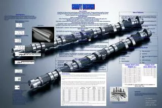
Torsional stiffness and inertia figures Torsional stiffness of a cylindrical piece (shaft part) follows equation: k = πD4G/32b, where D = diameter, b = length, G = material shear modulus. Equations are available for conical pieces and sectional changes. Often equations result in too high stiffness. Inertia of a cylindrical piece I = πD4bρ/32, where D = diameter, b = lenght (thickness), ρ = material density. Stiffness grows in 4th power of diameter, and linear to length inverter Inertia grows in 4th power of diameter, and linear to length Complicated geometrical forms inertia and stiffness figures are supplied by the component manufacturer.
MT Parita mass elastic system Inertia kgm2, Stiffness MNm/rad Stiffness 2400 1671 1671 1671 2503 4438 6608 440 480 Inertia 420 12500 12500 12500 12500 5666 21650 770 1500 87050 Nro 1 2 3 4 5 6 7 8 9 10 Item Flange Cylinder 1 Cylinder2 Cylinder3 Cylinder4. Camshaft drive Flywheel Flange Flange coupling Propeller Propeller inertia includes 18% of entrained water Engine designer supplies inertia and stiffness figures. Shaft line figures follow the basic equations.
Frequency chart, MS Parita Vibration frequency, cpm Orders 12 11 10 1000 900 800 700 600 500 400 300 200100 98765 4321 The reddish horisontal lines are the calculted two natural frequnecies – independent on revolution speed 20 30 40 50 60 70 80 90 100 rpm Order are multiplies of the revolution speed. E.g. during one crank shaft revolution the 3rd order vibration makes 3 full cycles (sinus waves)
MT Tervi mass elastic Inertia kgm2, Stiffness MNm/rad Damper Inertia 32500 1737 17500 17500 17500 17500 17500 7666 21650 770 1500 87050 Nro 1 2 3 4 5 6 7 8 9 10 11 12 Item Damper sec. Damper pri. Cylinder 1 Cylinder2 Cylinder3 Cylinder4. Cylinder5 Can shaft drive Flywheel Flange OK -coupling Propeller Stiffness 40 2400 1671 1671 1671 1671 2503 4438 8608 144 132 Propeller inertia includes 18% of entrained water Engine designer supplies inertia and stiffness figures. Shafting figures follow the basic equations.
Frequency chart, MS Tervi Vibration frequency, cpm Orders 12 11 10 1000 900 800 700 600 500 400 300 200100 98765 4321 The reddish horisontal lines are the calculated two natural frequencies – independent on revolution speed 20 30 40 50 60 70 80 90 100 rpm Order are multiplies of the revolution speed. E.g. during one crank shaft revolution the 3rd order vibration makes 3 full cycles (sinus waves)
MT Tervi mass elastic diagram Inertia kgm2, Stiffness MNm/rad Damper Inertia 32500 1737 17500 17500 17500 17500 17500 7666 21650 770 1500 87050 Nro 1 2 3 4 5 6 7 8 9 10 11 12 Item Damper sec. Damper pri. Cylinder 1 Cylinder2 Cylinder3 Cylinder4. Cylinder5 Can shaft drive Flywheel Flange OK -coupling Propeller Stiffness 40 2400 1671 1671 1671 1671 2503 4438 8608 144 132 Propeller inertia includes 18% of entrained water Engine designer supplies inertia and stiffness figures. Shafting figures follow the basic equations.
Frequency chaft, MS Tervi Vibration frequency, cpm Orders 12 11 10 1000 900 800 700 600 500 400 300 200100 98765 4321 The reddish horisontal lines are the calculated two natural frequencies – independent on revolution speed 20 30 40 50 60 70 80 90 100 rpm Order are multiplies of the revolution speed. E.g. during one crank shaft revolution the 3rd order vibration makes 3 full cycles (sinus waves)
Real vibration form Real systems have always considerable vibration damping. It lowers the resonance peaks but also affects the vibration phase. System free ends do not reach their extreme position simultaneously but there is phase difference. Simple chain of four lumped inertias 'Node' is the point where angual amplitude reaches minimum – but seldom amplitude is = 0
Torsional vibrations Natural vibration forms, MS Dredge Queen ( CPM= cycles per minute ) Lowest natural mode at 306 cpm. Node at generator branch coupling. Second natural mode at 435 cpm. Nodes at generator and main coupling
Torsional vibrations Natural vibration forms ( CPM= cycles per minute ) Third natural mode at 1152 cpm. Nodes at generator and main couplings and shaftline Fourth natural mode at 2560 cpm. Nodes at both couplings, shaftline and tors. damper springs. Fifth natural mode at 2880 cpm. Nodes at both couplings, shaftline, damper and crankshaft.
MS Dredge Queen vibration model Inertia 87 13 110 70 184 11 56 100 43 623 175 435 5140 11 18 3.5 4 272 Nro 1 2 3-11 12 13 14 15 16 17 18 19 20 21 22 23 24 25 26 Name Damper sec. Damper pri. Cylinders 1-9 Camshaftdrive Flw + coupl. Coupling sec. Clutch Gear wheel Pinion Bullwheel Shaft mass 1 Shaft mass 2 Propeller Gear wheel Coupling pri Coupling sec Shaft mass Generator Stiffness 6.5 419 116 (290) 260 1.4 78 47 140- - 210 38 29 - 27 0.28 2.5 13 Inertia kgm2, Stiffness MNm/rad Damper contents NOTES: Figures refer to actual rev.speed of each shaft. Gear ratios: 16-22: 2.084 17-18: 0.346 Propeller inertia includes 25% water Gear
Single Cylinder Excitation Four stroke engine working cycle = 2 crankshaft revolutions Gas force Inertia force Tangential force Gas excitation Mass inertia excitation Resultant + 0 - Tangential force 0 180 360 540 720 Crankshaft angle degrees
Excitation Harmonic analysis of 4 stroke engine gas excitation Mean indicated pressure = positive work Replacement by Fourier series. order 1 has one full sinus cycle during one crankshaft revolution. Each component has different amplitude and phase angle. Note half orders! 0.5 1.0 1.5 2.0 2.5 Working cycle = 2 revolutions
Excitation Harmonic analysis of 2 stroke engine gas excitation No half ordersbecause engine cycle = crankshaft revolution 1.0 2.0 3.0 4.0 5.0 Working cycle = 1 revolution
Frequency chart, MS Dredge Queen Vibration frequency, cpm Orders 12 11.5 11 10.5 10 9.5 5000 4500 4000 3500 3000 2500 2000 1500 1000 500 9.08.58.07.57.06.5 6.05.5 5.0 4.54.03.5 3.02.52.0 1.51.00.5 Horizontal red lines are the 5 natural frequencies 100 150 200 250 300 350 400 450 500 550 rpm
Excitation Excitation from single cylinders are summed with phase shift related to the firing order. Example: 4 cylinder four stroke cycle engine Obviously cylinders balance each other and decrease torque variation. Accurate analysis requires look on the harmonic components. Phase shift is similar to firing interval 180o. 0 180 360 540 720 Crankshaft angle degrees
Excitation Order 1, 4 cylinder four stroke cycle engine Phase shift 180o is such that excitation from cylinders completely cancel each other. Phase shift Working cycle = 2 revolutions
Excitation Order 1, 4 cylinder four stroke cycle engine Phase shift 180o is such that excitation from cylinders completely cancel each other. RESULT Working cycle = 2 revolutions
Excitation Order 2, 4 cylinder four stroke cycle engine For this order phase shift is 360o = such that excitation from cylinders pile up =cumulate. Phase shift Working cycle = 2 revolutions
Excitation Order 2, 4 cylinder four stroke cycle engine For this order phase shift is 360o = such that excitation from cylinders pile up =cumulate. RESULT Working cycle = 2 revolutions
Excitation Vector sum indicates how strong excitation comes from the engine compared with single cylinder. In this calculation the strength of single cylinder is multiplied with the cylinder relative amplitude. Opposite phase in the vibration form is observed by negative amplitude value. 1.0 Order 1.0 Working cycle = 2 revolutions
Excitation Vector sum indicates how strong excitation comes from the engine compared with single cylinder. In this calculation the strength of single cylinder is multiplied with the cylinder relative amplitude. Opposite phase in the vibration form is observed by negative amplitude value. calculated vector sum here is 0.7, not 0. Similarly vector sum of order 2.0 is 2.3, not 4.0 Order 1.0 RESULT Working cycle = 2 revolutions
Calculation of vector sums Assume simple system consisting of 6 cylinder engine, short shaftline and generator, Fig. 1. Fig. 2 shows the single node torsional vibration mode (1st mode). The node point is on intermediate shaft. There is significant twist deformation also in crankshaft Fig. 1 Propulsion plant 1.0 Fig. 2 single node vibration
Calculation of vector sums Crankshaft of 2 stroke cycle 6 cylinder engine is in Fig. 3. Firing order is 1-5-3-4-2-6. Crankshaft of 4 stroke cycle 6 cylinder engine in Fig.4. Firing order is 1-3-5-6-4-2. There are alternative firing orders. They give even firing interval, but bring external engine unbalance 1 5 6 3 2 4 Fig. 3 2 strokeenginecrankshaft 1 6 3 4 5 2 Fig. 4 4 stroke crankshaft
Calculation of vector sums When highly elasticcoupling is added between the engine and shaftline, vibration form changes, Fig. 5. This natural frequency is much lower than in fig. 2. Crankshaft and shaftline behave as rigid bodies. Amplitudes at free ends are similar to fig. 1. Elastic coupling 1.0 Fig. 5 single node vibration form with elastic coupling
Torsional vibrations - Calculation of vector sums Engine excitation is split in harmonic components. For each harmonic order the phase angles between cylinders are modified, too. Angle is multiplied by the order. In Fig. 6 order is 3. Fig. 7 shows phase diagrams for 6 cylinder 2 stroke cycle engine. Fig 8. for 6 cylinder 4 stroke cycle engine. 1 1 5 4 Angle between cylinders 1 and 5 is 60o.3 *60o = 180o . Angle between cylinders 1 and 4 is 180o. 3 * 180o =180o. Fig. 6 phase angle calculation
5 6 3 2 4 Calculation of vector sums 1 3 1 2 4 1 Cylinders 2 5 4 6 3 5 6 Orders 1 7 2 8 3 9 1 3 1 1 2 3 4 5 6 6 5 4 6 2 5 2 3 4 Orders 4 10 5 11 Main 6 12 Fig. 7Main and side harmonic orders, 2 stroke engine
5 6 3 2 4 Calculation of vector sums 1 3 1 2 4 1 2 5 4 6 3 5 6 Orders 0.5 2.5 3.5 5.5 6.5 1 2 4 5 7 1.5 4.5 7.5 1 2 3 4 5 6 Main orders 3 6 9Fig. 8Main and side orders, four stroke cycle engine
Calculation of vector sums Fig. 9 shows vector sums for 6 cylinder four stroke cycle engine plant, calculated separately for each harmonic order. They are obtained by addition of single cylinder vectors... … which obtain their length from the relative cylinder amplitude (from Fig. 2) and their direction from phase diagram (from Fig. 8). Resultant vector R shows how big is the engine excitation.
Calculation of vector sums 6543 2 1 5 3 4 2 R = 4.18 2 6 4 4 6 3 1 2 1 3 1 5 6 5 R = 1.09 R = 0.20 R = 0.24 Harmonic 0.5 2.5 3.5 1 2 4 1.5 4.5 7.5 3 6orders 5.5 6.5 5 7 8 Fig. 9 Vector sums: one node vibration mode of Fig. 2, four stroke cycle engine without elastic coupling
Calculation of vector sums 65 43 21 2 5 3 4 5 6 3 R = 5.78 3 4 2 1 6 1 6 5 1 R = 0.02 R = 0.05 4 2 R = 0.18 Harmonic 0.5 2.5 3.5 1 2 4 1.5 4.5 7.5 3 6 orders 5.5 6.5 5 7 8 Figure 10 Vector sums: one node vibration mode of Fig. 5, 4 stroke cycle engine with elastic coupling
Calculation of vector sums Elastic coupling 1.0 Fig. 11 Second, two node vibration form with elastic coupling and 6-cylinder, 4 stroke cycle engine
Calculation of vector sums 65432 1 6 5 4R 3 2 1 2 2 5 6 3 3 1 R = 4.51 4 6 R=0.01 1 4 R=0.931 5 Downscaled to 50% R = 0.02 Harmonic 0.5 2.5 3.5 1 2 4 1.5 4.5 7.5 3 6 orders 5.5 6.5 5 7 8 Fig. 12 Vector sums: two node vibration mode of Fig. 11, 4 stroke cycle engine with elastic coupling
Vector sums MS Dregde Queen (zoomed detail area of three lowest vibration forms) 4.5 4.0 3.5 3.0 2.5 Orders 7.0 0.34 0.08 1.08 0.15 1152 cpm 2.0 1.5 1.0 0.014 0.02 435 cpm 0.17 0.08 0.007 306 cpm 0.5 200 250 300 350 400 450 500 550 rpm
Effect on engine load, misfiring When injection to a cylinder fails, pme drops by 90 %. Excitation drops by 50 … 80 %. If vector sum has been small (cylinders cancel each other), resultant grows 10 … 50 times higher. Stress level grows in same proportion. 0.5 1 1.50.52 46 ptan ptan Pme Fig 13 Tangential gas excitation depending on load (selected orders) Pme Fig 14 Misfiring decreases the excitation
Vector sums, MS Dredge Queen When crankshaft vibrates as a solid piece, cylinders cancel each other. Resultant vector is ~ 0 (except for main orders). This is good, as orders 0.5 - 1.5 have high gas excitation. When balance between cylinders is disturbed (misfiring), resulting vector sum raises to 0.9 causing high responses. Deformations in crankshaft (twist) grow together with frequency. Vector sum of main orders decrease while other orders increase. Typical for orders 4.5 - 7.5. Crankshaft stress is the critical issue. Damper is installed at crankshaft free end for protection, to reduce shear stress.
Damper Inertia ring = ‘seismic mass’ Steel springs Damper is tuned to a close frequency. Steel spring deformations consume vibration energy. Damper is not needed for 6-cylinder engine if large crankshaft diameter keeps the shear stress level low. Vee-engines are equivalent to in-line engines. Higher cylinder numbers are generally more difficult. Oil inlet Cranshaft free end flange Inner stern Outside diameter up to 1200 mm, for low speed engines 2000 mm
Crank shaft stresses , 6-cyl. low speed engine Order 6.0 shear stress without damper Shear stress amplitude MPa Permitted 80 Order 6.0 shear stress with damper 60 40 20 40 60 80 100 120 140 160 180 rpm Nominal speed