Download
1 / 13
380 likes | 2.15k Views
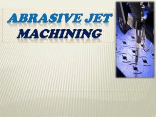
Abrasive Jet Machining (AJM) Case Studies. Some Studies on Abrasive Jet Machining Authors P.K. Ray and Dr. A.K. Paul Department of Mechanical Engineering Regional Engineering College Rourkela Journal of the Institution of Engineers (India) Volume 68, 1987. Introduction.

E N D
Abrasive Jet Machining (AJM) Case Studies
Some Studies on Abrasive Jet Machining Authors P.K. Ray and Dr. A.K. Paul Department of Mechanical Engineering Regional Engineering College Rourkela Journal of the Institution of Engineers (India) Volume 68, 1987
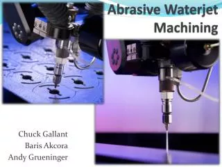
Introduction • An AJM setup may be of two types: • Using a vortex type mixing chamber – abrasive particles are carried by the vortex motion of the carrier gas. • Using a vibratory mixing chamber – abrasive particles are forced into the path of carrier gas by vibratory motion. • The erosion phenomenon may be considered as two phases. • Transportation problem - flow rate, direction and velocity of the impinging particles. • Problem of determining material removal rate or erosion rate. 3
Introduction • Erosion is a function of (i) Speed and angle of impact (ii) Ductility and/or brittleness of material as well the particles • Elasticity of the material • Shape and geometry of impinging particles • Impinging particle diameter to material thickness ratio • Average flow stress • Materials density • Stand-off distance. 4
Literature • According to Finnie (1960), MRR • Where, M & V - Mass flow rate and velocity of abrasives • - Angle of impingement • C, n - Constants • - Minimum flow stress of the materials • Sheldon & Finnie (1966) optimized ‘’ for max MRR. (For brittle - 90 and for ductile – 20 - 30) • Pandey (1977) and Bhatacharya (1976) studied the effect of abrasive flow rate (AFR) and stand-off distance (SOD) on MRR. • Authors - studied the effect of gas pressure on MRR, AFR and MRF (Material Removal Factor) during experimentation on an indigenous AJM setup developed in their lab. 5
Nozzle & Mixing Chamber SS Nozzle life – 2 hr Nozzle dia - 1.83 & 1.63 mm Abrasives – SiC (60 & 120 µm) Workpiece – porcelain Process – hole drilling 8
Effect of Pressure on MRR • MRR increases with pressure. • There is a threshold pressure below MRR is negligible. • MRR increases with increase in nozzle diameter, grain size and SOD. 9
Effect of SOD on MRR • They also stated as found by other researchers that MRR increases initially and remains constant for a small range. • Then it falls with further increase in SOD. 10
Effect of Pressure on AFR • It is found that AFR is proportional to the pressure. • As pressure increases, AFR increases. • Also, higher the grain size of abrasive particles, AFR is higher for the given pressure. 11
Effect of Pressure on MRF • MRF decreases with increase in pressure. • Quantity of material removed per gram of abrasive at a higher pressure is less than that at a lower pressure. • At higher pressure, AFR is higher – meaning more number of abrasive particles. • This reduces gas flow rate and affects the removal of debris (tiny particles from work). • Higher AFR – inter particle collision – loss of energy. • Cushioning effect of trapped abrasive particles. MRF = MRR / AFR 12
Conclusion • AJM with SiC – suitable for hard and brittle materials like porcelain. • Use of SS nozzle is justified by its low cost, though it has a very low life. • Nozzle changeover time – less than half a minute. • MRF – maximum for the pressure range of 2 – 3 kgf/cm2 • Increase in MRF beyond 4 kgf/cm2 pressure is marginal. • MRF & MRR – higher for higher SOD. • Thus, higher SOD is preferable where MRR is of prime importance. • In precision work, a higher pressure and a lower SOD may be adopted for better accuracy and penetration rate. 13