Download
1 / 17
170 likes | 311 Views
QUASI-ISOTHERMAL EXPANSION ENGINE FOR CRYOGENIC AUTOMOTIVE PROPULSION. CONTENTS. INTRODUCTION CRYOGENIC POWER CYCLE LIQUID NITROGEN PROPULSION SYSTEM ECONOMIZER WARMANT CIRCULATION THEORETICAL ANALYSIS OF EXPANDER CONCLUSION. INTRODUCTION.

E N D
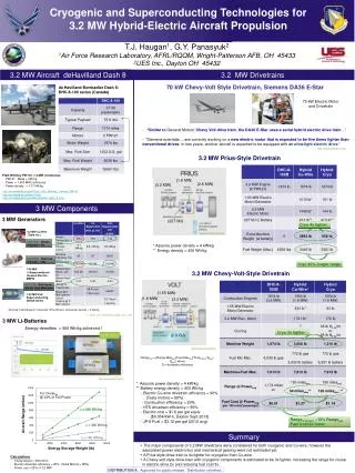
QUASI-ISOTHERMAL EXPANSION ENGINE FOR CRYOGENIC AUTOMOTIVE PROPULSION
CONTENTS • INTRODUCTION • CRYOGENIC POWER CYCLE • LIQUID NITROGEN PROPULSION SYSTEM • ECONOMIZER • WARMANT CIRCULATION • THEORETICAL ANALYSIS OF EXPANDER • CONCLUSION
INTRODUCTION • The potential of cryogenic energy storage for automotive propulsion as an alternative to the electrochemical batteries for zero-emission vehicles (ZEV). • It is anticipated that use of an inert cryogen, such as liquid nitrogen(LN2), as an energy storage would not pose any environmental burden, and in particular would avoid the issues of heavy metals pollution associated with lead-acid batteries.
CRYOGENIC POWER CYCLE • The cryogen “fuel” is stored in a vacuum jacketed vessel which has appropriate relief valves to safely accommodate boiloff. • A cryopump pressurizes the fluid to a level somewhat above the injection pressure of the expander to make up pressure loss in the heat exchanger system. • Turbines and either rotary or reciprocating fixed-displacement engines are appropriate expanders. • The shaft power from the expander is then readily applied for vehicle propulsion
WARMANT CIRCULATION • A “warmant” fluid is circulated through the expander walls to maintain them at near ambient temperature . • The warmant must be pumped through another heat exchanger system to efficiently conduct ambient heat into the engine. • A quasiisothermalreciprocating expander is proposed for this embodiment and its work output is transmitted to the wheels by means of a conventional transmission. • Under cruising operating conditions the propulsion system would realize an energy density of 245 kJ/kg-LN2 which makes it competitive with the best of lead-acid batteries being used today.
THEORETICAL ANALYSIS OF EXPANDER The thermodynamic simulation of a reciprocating expander has been developed to examine the impact of various engine design and operational parameters on the LN2 consumption of an ambient powered cryomobile. • Reciprocating engine model • Piston cylinder heat transfer • Piston ring friction • Warmant circulation • Analytical procedure
RECIPROCATING ENGINE MODEL • A one-zone, time-dependent analysis is applied on the control volume bounded by the piston and cylinder walls • The instantaneous state of the N2 gas in the control volume is determined from energy conservation and the ideal gas equation of state. The energy equation for the cylinder contents is expressed as • dP/dθ = (γ-1) / V {dQ/dθ - γ / (γ-1) P dV/dθ+dmi/dt hi - dme/dt he}
PISTON CYLINDER HEAT TRANSFER • In order to evaluate the trade off between bore, stroke, and revolution rate of a practical reciprocating expander, a means for estimating the heat transfer rate to the N2 during the expansion process is required. • For purposes of this study the heat transfer from the cylinder walls is assumed to be similar to turbulent heating of gas in a tube as follows: Nud~ Red m Prn • The corresponding heattransferis: dQ/dt= hx Aw (Tw - T)
PISTON RING FRICTION • The lost work due to piston ring friction is accounted for since it is expected to be highly dependent on the cylinder aspect ratio. • Thus the differential element of friction work δWffor the compression ring can be expressed as: δWf= μr P π d trδS
WARMANT CIRCULATION SYSTEM • The Warmantfluid is assumed to be a standard antifreeze mixture of water and ethylene-glycol. • Heating of Warmantin the ambient heat exchanger is governed by turbulent duct flow and the friction factor f is determined from Reynold’s analogy as follows: f / 8 = St Pr2/3
ANALYTICAL PROCEDURE • The analysis proceeds by first computing the temperature and pressure history for a fixed mass of gas undergoing expansion in a cylinder having a uniform wall temperature that is fixed at some point below ambient. • The indicated work of the pressure-volume diagrams for the adiabatic and isothermal cycles are compared to the corresponding analytical values to insure sufficiently small steps are used for the integration.
CONCLUSION • The potential for utilizing the available energy of liquid nitrogen for automotive propulsion looks very promising. • Heat transfer calculations of a quasi-isothermal reciprocating engine that has a heater core imbedded within its expansion chamber indicate that nearly 85% of the performance of an ideal isothermal power cycle can be attained.
REFERENCES • Knowlen, C., Hertzberg. A. and Mattick, A.T., “Cryogenic Automotive Propulsion,” AIAA Paper 94-4224, 29th I.E.C.E.C., 1994. • “Quasi-Isothermal Expansion Engines for Liquid Nitrogen Automotive Propulsion”,C. Knowlen, J. Williams, A.T. Mattick, H. Deparis, and A. Hertzberg