Download
1 / 17
330 likes | 699 Views
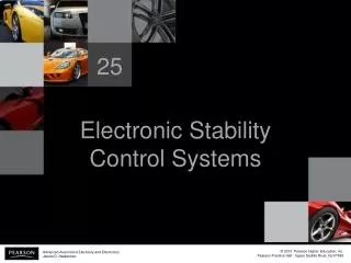
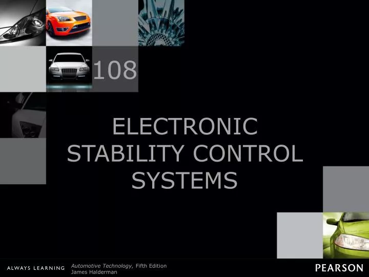
108. ELECTRONIC STABILITY CONTROL SYSTEMS. Figure 108-1 The electronic stability control (ESC) system applies individual wheel brakes to keep the vehicle under control of the driver.

E N D
108 ELECTRONIC STABILITY CONTROL SYSTEMS
Figure 108-1 The electronic stability control (ESC) system applies individual wheel brakes to keep the vehicle under control of the driver.
Figure 108-2 The sine with dwell test is designed to test the electronic stability control (ESC) system to determine if the system can keep the vehicle under control.
FREQUENTLY ASKED QUESTION: Can a Vehicle with a Modified Suspension Pass the Test? Yes, if the system is properly engineered. To be sure, check with the company offering a suspension kit to verify that the vehicle will still be able to pass the sine with dwell (SWD) test. This ensures that any changes are within the range where the ESC system can control the vehicle during emergency maneuvers. - SEE FIGURE 108–3 .
Figure 108-3 Using a simulator is the most cost-effective way for vehicle and aftermarket suspension manufacturers to check that the vehicle is able to perform within the FMVSS No. 126 standard for vehicle stability.
Figure 108-4 The hand-wheel position sensor is usually located at the base of the steering column.
Figure 108-5 Hand-wheel (steering wheel) position sensor schematic.
Figure 108-6 The VS sensor information is transmitted to the EBCM by Class 2 serial data.
Figure 108-7 A schematic showing the lateral acceleration sensor and EBCM.
TECH TIP: Quick and Easy Lateral Acceleration Sensor Test Most factory scan tools will display the value of sensors, including the lateral acceleration sensor. However, the sensor value will read zero unless the vehicle is cornering. A quick and easy test of the sensor is to simply unbolt the sensor and rotate it 90 degrees with the key on engine off. - SEE FIGURE 108–8 . Now the sensor is measuring the force of gravity and should display 1.0 G on the scan tool. If the sensor does not read close to 1.0 G or reads zero all of the time, the sensor or the wiring is defective.
Figure 108-8 The lateral accelerometer sensor (G-sensor) is usually located under the center console.
Figure 108-9 Yaw rate sensor showing the typical locations and schematic.
Figure 108-10 Typical traction control system that uses wheel speed sensor information and the engine controller (PCM) to apply the brakes at lower speeds and also reduce engine power applied to the drive wheels.
Figure 108-11 Wheel speed sensor information is used to monitor if a drive wheel is starting to spin.
Figure 108-12 A traction control or low traction light on the dash is confusing to many drivers. When the lamp is on or flashing, it indicates that a low traction condition has been determined and the traction control system is working to restore traction. A flashing traction dash light does not indicate a fault.
FREQUENTLY ASKED QUESTION: Does Traction Control Engage Additional Drive Wheels? When the term traction control is used, many people think of four-wheel-drive or all-wheel-drive vehicles and powertrains. Instead of sending engine torque to other drive wheels, it is the purpose and function of the traction control system to prevent the drive wheel(s) from slipping during acceleration. A slipping tire has less traction than a nonslipping tire—therefore, if the tire can be kept from slipping (spinning), more traction will be available to propel the vehicle. Traction control works with the engine computer to reduce torque delivery from the engine, as well as the controller to apply the brakes to the spinning wheel if necessary to regain traction.
Figure 108-13 The use of a factory scan tool is often needed to diagnose the ESC system.