Download
1 / 28
310 likes | 522 Views
Visual Perception and Robotic Manipulation Springer Tracts in Advanced Robotics. Hybrid Position-Based Visual Servoing. Chapter 6. Intelligent Robotics Research Centre (IRRC) Department of Electrical and Computer Systems Engineering Monash University, Australia. Geoffrey Taylor

E N D
Visual Perception and Robotic Manipulation Springer Tracts in Advanced Robotics Hybrid Position-Based Visual Servoing Chapter 6 Intelligent Robotics Research Centre (IRRC) Department of Electrical and Computer Systems Engineering Monash University, Australia Geoffrey Taylor Lindsay Kleeman
Overview • Motivation for hybrid visual servoing • Visual measurements and online calibration • Kinematic measurements • Implementation of controller and IEKF • Experimental comparison of hybrid visual servoing with existing techniques
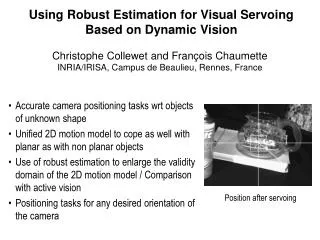
Motivation • Manipulation tasks for a humanoid robot are characterized by: • Autonomous planningfrom internal models • Arbitrarily large initial pose error • Background clutter and occluding obstacles • Cheap sensors camera model errors • Light, compliant limbs kinematic calibration errors Metalman: upper-torso humanoid hand-eye system
Visual Servoing • Image-based visual servoing (IBVS): • Robust to calibration errors if target image known • Depth of target must be estimated • Large pose error can cause unpredictable trajectory • Position-based visual servoing (PBVS): • Allows 3D trajectory planning • Sensitive to calibration errors • End-effector may leave field of view • Linear approximations (affine cameras, etc) • Deng et al (2002) suggest little difference between visual servoing schemes
Conventional PBVS • Endpoint open-loop (EOL): • Controller observes only the target • End-effector pose estimated using kinematic model and calibrated hand-eye transformation • Not affected by occlusion of the end-effector • Endpoint closed-loop (ECL): • Controller observes both target and end-effector • Less sensitive to kinematic calibration errors but fails when the end-effector is obscured • Accuracy depends on camera model and 3D pose reconstruction method
Proposed Scheme • Hybrid position-based visual servoing using fusion of visual and kinematic measurements: • Visual measurements provide accurate positioning • Kinematic measurements provide robustness to occlusions and clutter • End-effector pose is estimated from fused measure-ments using Iterated Extended Kalman Filter (IEKF) • Additional state variables included for on-line calibration of camera and kinematic models • Hybrid PBVS has the benefits of both EOL and ECL control and the deficiencies of neither.
Hybrid EOL ECL Coordinate Frames
PBVS Controller • Conventional approach (Hutchinson et al, 1999). • Control error (pose error): • WHE estimated by visual/kinematic fusion in IEKF. • Proportional velocity control signal:
Gripper tracked using active LED features, represented by an internal point model IEKF measurement model: Gi gi C Visual Measurements image plane camera centre 3D gripper model measurements
-* 2b* 2b affine reconstruction scaled reconstruction Camera Model Errors • In practical system, baseline and verge angle may not be known precisely. left image plane left camera centre right camera centre right image plane reconstruction
Camera Model Errors • How does scale error affect pose estimation? • Consider the case of translation only by TE: • Predicted measurements: • Actual measurements: • Relationship between actual and estimated pose: • Estimated pose for different objects in the same position with same scale error is different!
Camera Model Errors • Scale error will cause non-convergence of PBVS! • Although the estimated gripper and object frames align, the actual frames are not aligned.
Visual Measurements • To remove model errors, scale term is estimated by IEKF using modified measurement equation: • Scale estimate requires four observed points with at least one in each stereo field.
Kinematic Model • Kinematic measurement from PUMA is BHE • Measurement prediction (for IEKF): • Hand-eye transformation BHW is treated as a dynamic bias and estimated in the IEKF • Estimating BHW requires visual estimation of WHE, and is therefore dropped from the state vector if the gripper is obscured.
Kalman Filter • Kalman filter state vector (position, velocity, calibration parameters): • Measurement vector (visual + kinematic): • Dynamic models: • Constant velocity model for pose • Static model for calibration parameters • Initial state from kinematic measurements.
Constraints • Three points required for visual pose recovery • Stereo measurements required for scale estimation • LED association required multiple observed LEDs • Estimation of BHW requires visual observations • Use a hierarchy of estimators (nL,R = no. points): • nL,R < 3: EOL control, no estimation of K1 or BHW • nL > 3 xornR > 3: Hybrid control, no K1 • nL,R > 3: Hybrid control (visual + kinematic) • Excluded state variables are discarded by setting rows and columns of Jacobian to zero
Observed LEDs Predicted LEDs LED Measurement • LEDs centroids measured with red colour filter • Measured and model LEDs associated using a global matching procedure. • Robust global matching requires 3 LEDs.
Experimental Results • Positioning experiment: • Align midpoint between thumb and forefinger at coloured marker A • Align thumb and forefingeron line between A and B • Accuracy evaluation: • Translation error: distance between midpoint of thumb/forefinger and A • Orientation error: angle between line joining thumb/forefinger and line joining A/B
Positioning Accuracy Hybrid controller, final pose (right camera only) Hybrid controller, initial pose (right camera only)
Positioning Accuracy ECL controller, final pose (right camera only) EOL controller, final pose (right camera only)
Positioning Accuracy • Accuracy measured over 5 trial per controller.
Tracking Robustness Initial pose: gripper outside FOV (ECL control) Gripper enters field of view (Hybrid control, stereo) Final pose: gripper obscured (Hybrid control, mono)
Tracking Robustness Hybrid stereo Hybrid mono Hybrid stereo Hybrid mono EOL EOL Translational component of pose error Estimated scale (camera calibration parameter)
Baseline Error • Error introduced in calibrated baseline: • Baseline scaled between 0.7 to 1.5 • Hybrid PBVS performance in presence of error:
Verge Error • Error introduced in calibrated verge: • Offset between –6 to +8 degrees • Hybrid PBVS performance in presence of error:
Conclusions • We have proposed a hybrid PBVS scheme to solve problems in real-world tasks: • Kinematic measurements overcome occlusions • Visual measurements improve accuracy and overcome calibration errors • Experimental results verify the increased accuracy and robustness compared to conventional methods.