Download

1 / 36
360 likes | 464 Views
Compton Schemes for Polarised Positrons. Introduction. Compton based positron sources Introduction: Basics and nomenclature. Compton schemes are based on the following steps:

E N D
Compton Schemes for Polarised Positrons Alessandro Variola LAL -Orsay
Introduction Alessandro Variola LAL -Orsay
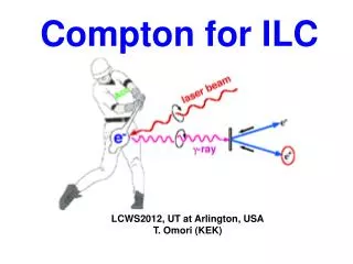
Compton based positron sourcesIntroduction: Basics and nomenclature • Compton schemes are based on the following steps: • An high energy electron beam collide with a (or more) light pulse. This electron beam is called “drive” or “Compton” beam. The corresponding machine is called the “Driver” • In the collision gammas are created (Compton effect). If the light pulse is circularly polarized the positrons will be polarized. Light linear polarization will result in an un-polarized positron beam. • These gammas impinge on a target and it is converted in e+ / e- pairs. The target is called “converter”. • Pairs are collected by a capture system (capture section). • After capture the particles are post accelerated and subsequently the positrons are separated from the electrons. • Positrons bunches are injected in the accumulator/damping ring. Due to Compton peculiarities stacking is probably required. Polarised positrons => The Alternative for polarised positrons is the undulator solution : undulator in the main beam arm @ very high energy to produce the gamma. So the driver is the main electron beam. Alessandro Variola LAL -Orsay
BASIC SCHEME W Ti Alloy W-Re Post Acceleration Linac Driver Positron Accumulator Target Post Acceleration 250 MeV Capture Transfer – Post acceleration Linac LINAC + CO2 Lasers + regenerating cavity Ring + Yag laser + Fabry Perot cavity ERL + Yag laser + Fabry Perot cavity AMD QWT Lithium Lens Damping Ring Alessandro Variola LAL -Orsay
Basic Idea : Have a Compton effect based polarized positron source • Advantages in respect the undulator schemes : -Independent system -Easy polarization flip @ 5Hz + non polarized (linear laser polarization). -Higher polarization possible (>70%) -Not disturbing the main beam -Operability of the positron arm (especially low energy operation) -Not considerable target heat problem (slow e+ production even Linac scheme) -Wide Applications in many fields -If ring/ERL can be shared with gamma factory -depending on the schemes and on choices, part of the Compton driver can be integrated in the e- Linac Alessandro Variola LAL -Orsay
Compton problem • What is the problem of a Compton based polarised positron source? Photon/collision = s ne ng foverlap where s = = 6.65 10-29m EXTREMELY LOW. So to compensate, as far as the single collision is concerned, it is evident that we have to increase the densities of the photons and electrons bunches and optimise the collision overlap. => ACCELERATORS TECH,LASER + OPTICAL CAVITIES And…stacking!!!!!! And….High flux of gammas cannot cross cavities mirrors : Holes or crossing angle in collision (decrease in the cross section). Alessandro Variola LAL -Orsay
The main question isWhat is the best driver? Parameters in the game : Alessandro Variola LAL -Orsay
DRIVERS LINAC Advantages : Drive beam => low emittance beam, short bunch, possibility of head on collision, no reusing after collision, easy AMD (pulsed regime), good for no stacking Disadvantage : Not high charge as ring, difficult high polarisation, pulsed or / low frep CO2 + regenerative cavity Advantages : Exist with very high pulse power, 10 times more photons in respect the Yag at the same power Disadvantages: pulsed or / low frep, need regenerative cavity (to be tested at high power), bigger waist _______________________________________________________________________________________ RING : Advantages : High charge per bunch, very high frep (possible CW),, very low emittances, good polarisation. Disadvantage : Long bunches (need compression or crab), need reusing (Compton regime), crossing angle, stacking ERL : Advantages : Short bunches, high frep (possible CW),, possible very high polarisation, no reusing (only re-circulation) Disadvantages : low charge, crossing angle, capture section (CW), stacking YAG + FP Advantages : Very high frep (possible CW),High power fiber laser very promising, possible very high gain in the cavity, very small waist. Disadvantages : Crossing angle, high power /pulse @ high frep to be demonstrated, less photon / energy in respect to CO2 Alessandro Variola LAL -Orsay
Compton Schemes are not mature now !! • Needed R&D • Both in drivers & Lasers Alessandro Variola LAL -Orsay
Compton schemes are very attractive but needs Drivers & Laser R&D • All Compton schemes need R&D • High charge/bunch ERL • Ring stability under Compton regime • Very high charge/bunch e- guns • CO2 lasers + regenerative cavities • Fiber lasers + FP cavities We must demonstrate light pulse circulating in the Joule regime (@ different frep) Alessandro Variola LAL -Orsay
Example for drivers….future projects Alessandro Variola LAL -Orsay
EXAMPLE : FIBER LASER R&D for the kW regime + lock to FP cavity Alessandro Variola LAL -Orsay
Present R&D at Orsay (funded by EUROTEV & IN2P3:CNRS) • 2 Goals: 1)To operate a very high finesse Fabry-Perot cavity in pulsed regime • 2 mirrors cavities Gain: 104-105 • NOW @ 103 2) reduction of the laser beam size (waist @ ~ 10 mm) • 4 mirrors non-planar cavity • NOW @ < 20 mm Alessandro Variola LAL -Orsay
CO2 laser+cavity Then pass to 4 mirrors Regenerative cavity for Joule regimes M.Shverdin Alessandro Variola LAL -Orsay
Important : Compton cross section parameters optimizationdepending on the driver (scheme) Alessandro Variola LAL -Orsay
First parenthesis Compton Cross Section Analysis Energy & Cutoff This must be taken into account Since the Acceptance of the AMD is limited. Higher the energy cut for photons higher the positrons one => reducing of the capture efficiency No gain increasing the beam energy Photon energy cut increases and so does the energy spread of the produced positrons Alessandro Variola LAL -Orsay
Crossing Angle Alessandro Variola LAL -Orsay
Bunch Length & AngleCorrelation -Reducing the bunch length gives an important gain ( ~ linear) -The shorter the bunch length the less sensitive to the angle loss effect Alessandro Variola LAL -Orsay
BUT…….Crab Angle Optimisation q0=8o Alessandro Variola LAL -Orsay
Best Crab Taking into account the 8 deg case it is already a gain factor ~ 4.5 - Crabbing is important - Best crab is at ~ crossing angle/2 - Shorter bunches are less sensitive to crab Alessandro Variola LAL -Orsay
Long Electron Beam – Short Laser Pulse: effect on laser waist (hourglass) Increasing the laser waist does not entail a dramatic loss Alessandro Variola LAL -Orsay
Round Beam – Flat Beam The reference for the flat beam is always the case illustrated before (5 and 20 mm) If we vary the beta functions at the collision point to make the electron beam round we have that: Round beam s Rate round / Rate flat No evident need for a round beam Alessandro Variola LAL -Orsay
Summary on cross section • 1) Short drive beam bunch length and short laser pulse ok. • 2) Long bunch and short laser pulse + angle = loss (can be considerable) • 3) Solutions : 1 - bunch compression, 2 - crab • 4) Varying waist or bunch aspect ratio (when the waist is fixed) not drastic. Alessandro Variola LAL -Orsay
REMEMBER : For the three schemes Linac+CO2 : short bunch, head on, stacking limited, at present charge per bunch 3 nC Ring + YAG : long bunch, crossing angle,beam re using , high frep for stacking, 10nC ERL+Yag : short bunch, high frep for stacking, 1-2 nC, crossing angle Alessandro Variola LAL -Orsay
Examples Alessandro Variola LAL -Orsay
ILC Snowmass proposal Alessandro Variola LAL -Orsay
EXAMPLES : CAIN Simulation=> LINAC & ERL Beam STATISTICS +++Right-going photon 25034 macro particles 1.562D+09 real Average (t,x,y,s) 4.000D-04 5.161D-08 1.431D-08 4.002D-04 m R.m.s. (t,x,y,s) 1.138D-17 8.025D-06 4.693D-06 1.711D-04 m Min (t,x,y,s) 4.000D-04 -3.212D-05 -2.013D-05 -2.618D-04 m Max (t,x,y,s) 4.000D-04 3.005D-05 2.815D-05 1.070D-03 m Average (En,Px,Py,Ps) 1.474D+07 1.699D+01 3.052D+01 1.474D+07 eV R.m.s. (En,Px,Py,Ps) 9.279D+06 2.658D+03 2.672D+03 9.279D+06 eV Min (En,Px,Py,Ps) 3.095D+02 -7.827D+03 -8.248D+03 3.082D+02 eV Max (En,Px,Py,Ps) 2.987D+07 8.207D+03 8.557D+03 2.987D+07 eV Stokes (|Xi|,Xi1,Xi2,Xi3) 0.00709 0.00128 0.00675 0.00175 Linac - ERL solution Can we compensate the charge reduction with bunch compression? • Laser power density 1.90349132D+21 • Laser pulse Energy [Joule]= 6.00000000D-01 • Laser pulse length [m]= 2.40000000D-04 • Laser pulse wavelength [m= 1.06000000D-06 • Laser waist size [m]= 1.00000000D-05 • Laser Rayleigh length [m]= 2.96376665D-04 • Compton cut off [x beam energy]= 2.27627018D-02 • Beam Energy [eV]= 1.30000000D+09 • Particles per bunch9.36000000D+09 • Collision beta function x= 1.60000000D-01 • Collision beta function y= 1.60000000D-01 • Beam size sigma x [m] = 1.00000000D-05 • Beam size sigma y [m] = 1.00000000D-05 • Beam length sigma z [m] = 2.00000000D-04 • Emittance x= 6.25000000D-10 • Emittance y= 6.25000000D-10 • Energy Spread= 3.00000000D-03 • Collision angle [rad]= 8.72664626D-02 • *********************************** • *********************************** @ 1.8 nC Alessandro Variola LAL -Orsay
CW MODE => Selection of bunch repetition: frep 3 factors to determine frep 163 MHz preferable ERL bunch charge 40.8 MHz preferable Laser & optical cavity e+ stacking T Omori 40.8 MHz preferable Alessandro Variola LAL -Orsay
CLIC Alessandro Variola LAL -Orsay
Main beam parameters comparison At the entrance of the Main Linac for e- and e+ Alessandro Variola LAL -Orsay
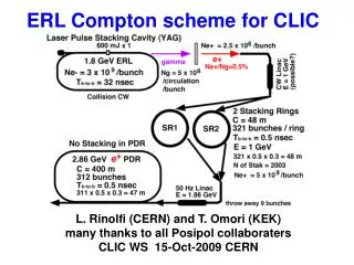
30 m 30 m e- Main Linac e+ Main Linac e- BC2 e+ BC2 12 GHz 2.3 GV 12 GHz 2.3 GV 12 GHz, 100 MV/m, 21 km 12 GHz, 100 MV/m, 21 km 9 GeV 48 km 3 TeV Laser Compton configuration Booster Linac 6.6 GeV 3 GHz 360 m e+ BC1 e- BC1 10 m 10 m 3 GHz 162 MV 3 GHz 162 MV 2.424 GeV 360 m 2.424 GeV 360 m e+ DR e- DR e+ PDR and Accumulator ring e- PDR 2.424 GeV 2.424 GeV Injector Linac 2.2 GeV 1.5 GHz RF gun 150 m e- Drive Linac 1.3 GeV Compton ring e+ Target Laser 3 GHz Pre-injector Linac for e+ 200 MeV Pre-injector Linac for e- 200 MeV g DC gun Polarized e- Stacking cavity 1.5 GHz 1.5 GHz 15 m 15 m EXAMPLE : DRIVER = RING Louis Rinolfi Laser The CLIC Injector complex Alessandro Variola LAL -Orsay
Scaling the CLIC Parameters • Need : 300 bunches of 4 109 positrons @ 50 Hz. • Assuming capture efficiency ~ 2% => 2 1011 gammas per bunch ( the double with safety margin) • Case => All photons in one shot , CO2 Laser + Linac. @ 1J/1nC/1 cavity ~ 6 109 gammas • So 10 cavity => 3-4 nC if capture efficiency • is maintained (difficult). Think about a • Ring but expensive (Energy) • Case=> Low stacking in accumulator, Ring + Yag, @ 0.6 J, 10nC/ 1 cavity ~ 3 109gammas • 10 cavities => needs 4-10 STACKING in the accumulator • Case=> High stacking in accumulator, ERL + YAG, @ 0.6 J, 2nC/ 1 cavity ~ 1 109 gammas (short bunch effect) • 10 cavities => needs 20-50 STACKING in the accumulator Alessandro Variola LAL -Orsay
EXAMPLES : AMD CAPTURE EFFICIENCY (Short bunches) Alessandro Variola LAL -Orsay
Stacking Constraints • frep is not a problem for production • Can be for injection • LARGE acceptance (determined by AMD and injection energy) • Damping time • Syncro between accumulator and damping ring (can we use the damping ring as a second accumulation ring by stacking?) Alessandro Variola LAL -Orsay
Conclusions • Compton Schemes are extremely attractive for the polarized positron sources since they present many advantages on the undulator schemes • Need of strong R&D on lasers and cavities • Careful optimization of the interaction point is necessary • CLIC is a machine that can surely benefit from these schemes. • What scheme to chose? It depends from the future R&D results and the accumulator design. If large acceptance => stacking so ERL or Ring allowing high degree of polarization. If not => Linac with anyway polarization bigger than 40% Alessandro Variola LAL -Orsay
Thanks for your attention • Thanks to all the colleagues that provided the transparencies Alessandro Variola LAL -Orsay