Download
1 / 40
410 likes | 864 Views
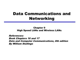
Data Communications and Networking. Chapter 9 High Speed LAN s and Wireless LANs References: Book Chapters 16 and 17 Data and Computer Communications, 8th edition By William Stallings. Outline. Fundamentals of Ethernet ALOHA, slotted ALOHA, CSMA CSMA/CD Ethernet Examples

E N D
Data Communications and Networking Chapter 9 High Speed LANs and Wireless LANs References: Book Chapters 16 and 17 Data and Computer Communications, 8th edition By William Stallings
Outline • Fundamentals of Ethernet • ALOHA, slotted ALOHA, CSMA • CSMA/CD • Ethernet Examples • 10-Mbps Ethernet • Fast Ethernet • Gigabit Ethernet • 10-Gbps Ethernet • 802.11 Wireless LANs
Ethernet • Most widely used high-speed LANs • Ethernet (10Mbps, 100Mbps, 1Gbps, 10Gbps) • Fibre channel • High-speed wireless LANs • Ethernet protocol is developed by IEEE 802.3 standards committee, consisting of • Medium Access Control (MAC) Layer (CSMA/CD protocol) • the key part of this chapter • Physical Layer • Earlier MAC schemes: • ALOHA • Slotted ALOHA • CSMA
ALOHA • ALOHA protocol is developed for packet radio networks, but applicable to any shared transmission medium. • A number of stations share the transmission medium. Two or more simultaneous transmissions will cause a collision. • Sender • When station has frame, it sends • Station listens for an amount of time • If its hears an ACK, fine. If not, it retransmits the frame after a random time • If no ACK after several transmissions, it gives up • Frame check sequence can be used for error detection • Receiver • If frame is OK and address matches receiver, sends ACK • Otherwise, ignores this frame and does nothing • Frame may be damaged by noise or by another station transmitting at the same time (collision). Overlap of frames also causes collision. • ALOHA is simple, but very inefficient • Assuming random traffic, the maximum channel utilization is only about 18%
Slotted ALOHA • To improve efficiency, a modification of ALOHA, known as slotted ALOHA, was developed. • Time is organized into uniform slots whose size equals the frame transmission time • Need a central clock (or other sync mechanism) • Transmission begins only at a slot boundary • Consequence: frames either miss or overlap totally • Maximum channel utilization can be improved to about 37%
CSMA • Why ALOHA and slotted ALOHA are so inefficient? • Stations don’t check the channel status. They just send out frames without considering whether the channel is free or not, which creates too many collisions. • In fact, it is not difficult for a station to “sense” the channel status (free or not). • CSMA: Carrier Sense Multiple Access • Stations listen to the channel (carrier sense) • Stations “know” whether the channel is free or not • Stations transmit only if the channel is free • Collisions become rare • Only if two or more stations attempt to transmit at about the same time, collisions could happen.
CSMA (Cont.) • In traditional LANs, propagation time is much less than frame transmission time • Remark: this may not be true for 1Gbps and 10Gbps Ethernet • All stations know that a transmission has started almost immediately by “carrier sense” • Details of CSMA • Stations first listen for clear medium (carrier sense) • If medium is idle, transmit the frame • If two or more stations start at about the same instant, there will be a collision. • To account for this, a station waits for an ACK • If no ACK after a reasonable time, then retransmit • What should a station do if the medium is found busy? • Three different approaches: nonpersistent CSMA, 1-persistent CSMA, and p-persistent CSMA
Nonpersistent CSMA • A station wishing to transmit listens to the medium and obeys the following rules: • If medium is idle, transmit; otherwise, go to step 2 • If medium is busy, wait an amount of time drawn from a probability distribution and repeat step 1 • The use of random delays reduces probability of collisions • Consider two stations become ready to transmit at about the same time while another transmission is in progress • If both stations delay the same amount of time before retrying, both will attempt to transmit at same time collision • Drawback: • Capacity is wasted because medium will generally remain idle following the end of a transmission, even if there are one or more stations waiting to transmit.
1-persistent CSMA • To avoid idle channel time, 1-persistent protocol can be used • A station wishing to transmit listens to the medium and obeys the following rules: • If medium is idle, transmit; otherwise, go to step 2 • If medium is busy, continue to listen until the channel is sensed idle; then transmit immediately. • 1-persistent stations are selfish • Drawback: • If two or more stations are waiting to transmit, a collision is guaranteed.
p-persistent CSMA • p-persistent CSMA is a compromise that attempts to reduce collisions, like nonpersistent, and reduce idle time, like 1-persistent • Rules: • If the medium is idle, transmit with probability p, and delay one time unit with probability (1 – p) • The time unit is typically equal to the maximum propagation delay • If the medium is busy, continue to listen until the channel is idle and repeat step 1 • If transmission is delayed one time unit, repeat step 1 • Question: • What is an effective value of p?
Value of p? • Assume n stations are waiting to transmit while a transmission is taking place • At the end of transmission, the expected number of stations attempting to transmit is the number of stations ready (i.e., n) times the probability of transmitting (i.e., p): np • If np > 1, on average there will be a collision • Repeated attempts to transmit almost guarantee more collisions • Retries compete with new transmissions from other stations • Eventually, all stations try to send • Continuous collisions; zero throughput • So np should be less than 1 for expected peaks of n • Drawback of p-persistent: • If heavy load is expected,p should be small such that np < 1. However, as p is made smaller, stations must wait longer to attempt transmission, which results in very long delays.
CSMA/CD: CSMA with Collision Detection • The problem of CSMA: • A collision occupies medium for the duration of a frame transmission, which is not good for long frames. • Collision Detection: • Stations listen whilst transmitting. If collision is detected, stop transmission immediately. • Rules of CSMA/CD: • If the medium is idle, transmit; otherwise, go to step 2 • If the medium is busy, continue to listen until the channel is idle, then transmit immediately • If a collision is detected during transmission, transmit a brief jamming signal to assure that all stations know that there has been a collision and then cease transmission • After transmitting the jamming signal, wait a random amount of time, referred to as backoff, then attempt to transmit again (repeat from step 1)
CSMA/CDOperation C detects a collision! A detects a collision!
Collision Detection The amount of time that it takes to detect a collision is no greater than twice the end-to-end propagation delay. Frames should be long enough to allow collision detection prior to the end of transmission. If shorter frames are used, then collision detection does not occur. For 10 and 100Mbps Ethernet, the frame length is at least 512 bits. For 1Gbps Ethernet, the frame length is at least 4096 bits, using carrier extension or frame bursting.
Which Persistence Algorithm? • IEEE 802.3 uses 1-persistent • Both nonpersistent and p-persistent have performance problems • 1-persistent seems to be more unstable than p-persistent, due to the greed of the stations • But wasted time due to collisions is short (if frames are long relative to propagation delay) • With random backoff, stations involved in a collision are unlikely to collide on next tries • To ensure backoff maintains stability, IEEE 802.3 and Ethernet use binary exponential backoff
Binary Exponential Backoff • Rules of binary exponential backoff: • A station attempts to transmit repeatedly in the face of repeated collisions • For the first 10 attempts, the mean value of the random delay is doubled • The mean value then remains the same for 6 additional attempts • After 16 unsuccessful attempts, the station gives up and reports an error • As congestion increases, stations back off by larger and larger amounts to reduce the probability of collision. • 1-persistent algorithm with binary exponential backoff is efficient over a wide range of loads • At low loads, 1-persistence guarantees that a station can seize channel as soon as the channel goes idle • At high loads, it is at least as stable as the other techniques • Problem: Backoff algorithm gives last-in, first-out effect • Stations with no or few collisions will have a chance to transmit before stations that have waited longer
IEEE 802.3 Frame Format ≥ ≥ Preamble: 7 octets of 10101010 SFD: 10101011 Length: the maximum frame size is 1518 octets, excluding the preamble and SFD. Pad: octets added to ensure that the frame is long enough for collision detection FCS: 32-bit CRC, based on all fields except preamble, SFD, and FCS
10Mbps Specification (Ethernet) • IEEE 802.3 defined a number of physical configurations. • The nation follows the rule of • <data rate in Mbps><Signaling method><Max segment length in hundreds of meters>
100Mbps Fast Ethernet • Fast Ethernet refers to a set of specifications developed by IEEE 802.3 committee to provide a low-cost, Ethernet-compatible LAN operating at 100 Mbps. • Use IEEE 802.3 MAC protocol and frame format • 100BASE-X refers to a set of options that use two physical links between nodes: one for ttransmission and one for reception • 100BASE-TX for twisted pair • 100BASE-FX for optical fiber • 100BASE-T4 can use Category 3 UTP cable • Uses four twisted-pair lines between nodes • Data transmission uses three pairs in one direction at a time • Star-wire topology • Similar to 10BASE-T
Gigabit Ethernet • The Gigabit Ethernet uses the same CSMA/CD frame format and MAC protocol as used in the 10Mbps and 100Mbps version of IEEE 802.3. • For shared-medium hub operation, there are two enhancements to the basic CSMA/CD • Carrier extension • Appends a set of special symbols to the end of short MAC frames so that the resulting block is at least 4096 bit-times in duration (512 bit-times for 10/100Mbps) • Frame bursting • Allows for multiple short frames to be transmitted consecutively (up to a limit) without giving up control for CSMA/CD between frames. It avoids the overhead of carrier extension when a single station has a number of small frames ready to send. • Not necessary for Ethernet switches because there is no contention for a shared medium.
10-Gbps Ethernet • 10-Gbps Ethernet can be used to provide high-speed, local backbone interconnection between large-capacity switches. • Our departmental Ethernet uses 10-Gbps Ethernet at the backbone.
10-Gbps Ethernet Configuration 10-Gbps Ethernet also targets at Metropolitan Area Networks (MANs) and WANs.
Wireless LANs • Wireless LAN makes use of a wireless transmission medium. • Wireless LAN applications • LAN Extension • Cross-building Interconnection • Nomadic Access • Ad Hoc Networking • An ad hoc network is a peer-to-peer network (without centralized server) set up temporarily to meet some immediate need.
WLAN Configurations (option1 of 2): Infrastructure Wireless LAN
Wireless LAN Technology • Infrared (IR) LANs • An individual cell of an IR LAN is limited to a single room, because infrared light does not penetrate opaque walls • Spread spectrum LANs • The most popular type • In United States, three microwave bands for unlicensed use • 915-MHz band (902-928 MHz) ---- 26 MHz of bandwidth • 2.4-GHz band (2.4-2.4835 GHz) ---- 83.5 MHz of bandwidth • 5.8-GHz band (5.725-5.825 GHz) ---- 100 MHz of bandwidth
IEEE 802.11 • IEEE 802.11 is devoted to wireless LANs. • Consists of MAC and physical layer protocols for wireless LANs • The Wi-Fi Alliance (Wi-Fi: Wireless Fidelity) • An industry consortium • To certify interoperability for 802.11 products • IEEE 802.11 Architecture • The smallest building block is Basic Service Set (BSS) • A number of stations executing the same MAC protocol • Shared wireless medium • BSS corresponds to a cell • A BSS may be isolated, or may connect to a Backbone Distribution System (DS) through an Access Point (AP) • AP functions as a bridge and a relay point • AP could be a station which has the logic to provide DS services • AP corresponds to a Control Module (CM) • DS can be a switch, wired network, or wireless network • An Extended Service Set (ESS) consists of two or more BSSs interconnected by a DS.
IEEE 802.11 Protocol Architecture Physical Layer
802.11 Physical Layer • Issued in four stages • First part in 1997 • IEEE 802.11 • Includes MAC layer and three physical layer specifications • Two in 2.4-GHz band and one infrared • All operating at 1 and 2 Mbps • Two additional parts in 1999 • IEEE 802.11a • 5-GHz band, data rate up to 54 Mbps • IEEE 802.11b • 2.4-GHz band, data rate at 5.5 and 11 Mbps • Most recent in 2002 • IEEE 802.11g extends IEEE 802.11b to higher data rates, up to 54 Mbps • At present • IEEE 802.11n: data rate up to hundreds of Mbps
Medium Access Control • MAC layer hasthree functions • Reliable data delivery • Different from Ethernet, wireless LANs suffer from considerable unreliability. • Access control • Distributed access • Centralized access • Security
Reliable Data Delivery • 802.11 physical and MAC layers subject to unreliability • Noise, interference, and other propagation effects result in loss of frames • Even with error-correction codes, frames may not successfully be received • 802.11 includes frame exchange protocol • Station receiving frame returns acknowledgment (ACK) frame • The exchange of these two frames is treated as atomic unit • Not interrupted byany other station • If no ACK frame received within short period of time, retransmit • To further enhance reliability, four-frame exchange may be used • Source issues a Request to Send (RTS) frame to destination • Destination responds with Clear to Send (CTS) • After receiving CTS, source transmits data • RTS and CTS notify other stations that a transmission is under way, so they refrain from transmission in order to avoid collision • Destination responds with ACK • The purpose of RTS/CTS • The collision time is shortened, because collision only occurs on the RTS frame, which is very short compared with data frames
A B C Hidden Terminal Problem A and B can hear each other. B and C can hear each other. But A and C cannot hear each other. When A is sending data to B, C cannot sense this activity and hence C is allowed to send data to B at the same time. This will cause a collision at B. collision Consider the effect of RTS/CTS: RTS alerts all stations within range of source (i.e., A) that exchange is under way; CTS alerts all stations within range of destination (i.e., B).
Medium Access Control • Two sublayers • Lower sublayer is distributed coordination function (DCF) • Uses a contention algorithm to provide access to all traffic • Higher sublayer is point coordination function (PCF) • Uses a centralized algorithm • Contention free • Implemented on top of DCF • Remark: PCF has not been popularly implemented in today’s 802.11 products. DCF is widely used.
Distributed Coordination Function: CSMA/CA • DCF sublayer uses CSMA/CA protocol, where CA refers to as Collision Avoidance • A station with a frame to transmit senses the medium. If the medium is idle, it waits to see if the medium remains idle for a time equals to a delay called Interframe Space (IFS). If so, the station may transmit immediately. • If the medium is busy, the station defers transmission and continues to monitor the medium until the current transmission is over. • Once the transmission is over, the station delays another IFS. If the medium remains idle for this period, then the station backs off a random amount of time and again senses the medium. If the medium is still idle, the station may transmit. During the backoff time, if the medium becomes busy, the backoff timer is halted and resumes when the medium becomes idle. • If the transmission is unsuccessful, which is determined by the absence of an ACK, then it is assumed that a collision has occurred. • To ensure that backoff maintains stability, binary exponential backoff is used. • Why notcollision detection? • Collision detection is not practical on wireless networks • The dynamic range of wireless signals is very large • The transmitting station cannot distinguish incoming weak signals from noise and/or effects of own transmission
IEEE 802.11 MAC Frame Format • Frame Control:Indicates the type of frame • control, management, or data • Control Frames: • RTS, CTS, ACK (Acknowledgement), etc. • Management Frames: • to manage communications between stations and APs.
MAC Frame Fields • Duration/Connection ID: • If used as duration field, indicates the time (in s) the channel will be allocated for successful transmission of a MAC frame • In some control frames, contains association or connection identifier • Addresses: • The number and meaning of the 48-bit address fields depend on context • source address, destination address, transmitteraddress, receiver address • Sequence Control: • 4-bit fragment number subfield used for fragmentation and reassembly • 12-bit sequence number used to number frames between given transmitter and receiver • Frame Body: • MSDU or a fragment of an MSDU • Frame Check Sequence: • 32-bit cyclic redundancy check