Download
1 / 24
250 likes | 552 Views
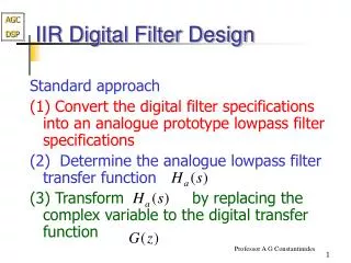
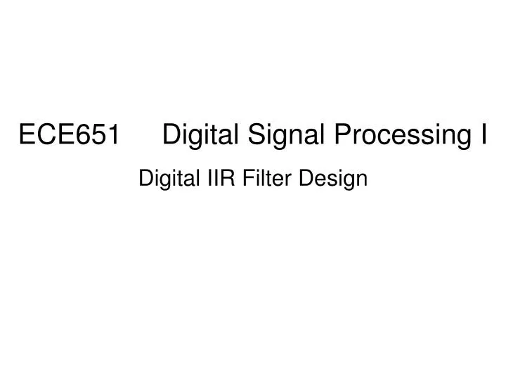
ECE651 Digital Signal Processing I Digital IIR Filter Design. Introduction Some Preliminaries on Analog Filters Digital IIR Filter Design (s – z) Impulse Invariance Transformation Bilinear Transformation Frequency Band Transformations Analog Domain (s – s )

E N D
ECE651 Digital Signal Processing I Digital IIR Filter Design
Introduction • Some Preliminaries on Analog Filters • Digital IIR Filter Design (s – z) • Impulse Invariance Transformation • Bilinear Transformation • Frequency Band Transformations • Analog Domain (s – s ) • Digital Domain (z – z)
Introduction Analog filter : Infinitely long impulse response S – Z (complex-valued mapping) Digital IIR filter : Infinitely long impulse response
Introduction • Advantages • Analog filter design tables available • Filter transformation (s – z) tables available • Frequency band transformation (s – s / z – z) available • Disadvantages • No control over the phase characteristics of the IIR filter • Magnitude – only design
Introduction • Other Design Approaches • Simultaneously approximate both the magnitude and the phase response • Require advanced optimization tools • Not covered in the class
Preliminaries On Analog Filters Analog lowpass filter specifications : passband ripple parameter A: stopband attenuation parameter : passband cutoff frequency (rad/sec) : stopband cutoff frequency (rad/sec)
Preliminaries On Analog Filters Analog lowpass filter specifications : passband ripple in dB : stopband attenuation in dB
Preliminaries On Analog Filters Analog lowpass filter system function • Poles and zeros of magnitude-squared function are distributed in a mirror-image symmetry with respect to the imaginary axis • For real filters, poles and zeros occur in complex conjugate pairs ( mirror symmetry with respect to real axis)
Preliminaries On Analog Filters Analog lowpass filter system function • Pick up poles On LHP • Pick up zeros on LHP or • Imaginary axis Causal Stable
Preliminaries On Analog Filters • Prototypeanalog filters • Butterworth • Chebyshev (Type I and II) • Elliptic
Preliminaries On Analog Filters Butterworth lowpass filters (Magnitude-Squared Response) The Cutoff frequency (rand/sec) N Theorder of the filter
Preliminaries On Analog Filters Butterworth lowpass filters(System Function)
Preliminaries On Analog Filters Butterworth lowpass filters (Design equations)
Digital IIR Filter Design • S - Z transformation • Complex-valued mappings • Derived by preserving different aspects of analog filters and digital filters
Digital IIR Filter Design • Impulse Invariance transformation • Preserve the shape of impulse response
Digital IIR Filter Design • Impulse Invariance transformation (Design Procedure) • (MATLAB function: impinvar) • Choose T and determine the analog frequencies • Design an analog filter using specifications • Partial fraction expansion • Transform analog poles into digital poles to obtain
Digital IIR Filter Design • Impulse Invariance transformation (Aliasing) >> f=0:0.01:5;T=0.1; >> z=exp(j*2*pi*f*T); >> zH=(1-0.8966./z)./(1-1.5595./z+0.6065./z./z); >> s=j*2*pi*f; >> sH=(1+s)./(s.^2+5*s+6); >> plot(f,abs(zH),f,abs(sH)/T);legend('Digitital','Analog') >>title('Magnitude Response of Analog and Digital IIR Filters')
Digital IIR Filter Design • Impulse Invariance transformation • Advantages: • Stable design • Analog frequency and digital frequency are linearly related • Disadvantage • Aliasing • Useful only when the analog filter is band-limited (LPF and BPF)
Digital IIR Filter Design • Bilinear transformation • Preserve the system function representation
Digital IIR Filter Design • Bilinear transformation (Design Procedure) • (MATLAB function: bilinear) • Choose T (1)and determine the analog frequencies • Design an analog filter using specifications • Bilinear transformation
Digital IIR Filter Design • Bilinear transformation • Advantages • Stable design • No aliasing • No restriction on the type of filters that can be transformed
Frequency DomainTransformations • Analog Domain
Frequency DomainTransformations • Digital Domain