Download

1 / 56
560 likes | 663 Views
Software Engineering. Natallia Kokash email: nkokash@liacs.nl. Agenda. Software Architecture Definition Architecture Design Viewpoints and view models Architectural styles Architecture assessment Software Design Principles Methods. Programmer’s approach to SD. Skip RE and design

E N D
Software Engineering Natallia Kokash email: nkokash@liacs.nl N. Kokash, Software Engineering
Agenda • Software Architecture • Definition • Architecture Design • Viewpoints and view models • Architectural styles • Architecture assessment • Software Design • Principles • Methods N. Kokash, Software Engineering
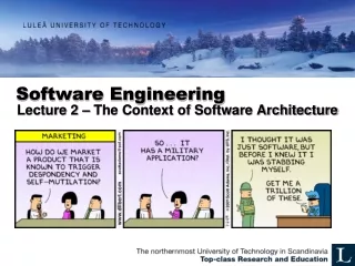
Programmer’s approach to SD • Skip RE and design • Start writing code • Design is a waste of time • We need to show something to the customer • We are judged by the amount of LOC/month • We know that the schedule is too tight… How is this different from eXtreme Programming? Another view: The longer you postpone coding, the sooner you will finish! N. Kokash, Software Engineering
Design principles Abstraction Modularity, coupling and cohesion Information hiding Limited complexity Hierarchical structure N. Kokash, Software Engineering
Abstraction • Procedural abstraction: • Natural consequence of stepwise refinement: name of procedure denotes sequence of actions • Data abstraction: • Aimed at finding a hierarchy in the data N. Kokash, Software Engineering
Coupling and cohesion • Cohesion: the glue that keeps a module together • Coupling: the strength of the connection between modules Structural criteria which tell us something about individual modules and their interconnections N. Kokash, Software Engineering
Cohesion types Coincidental (worst): arbitrarily parts (e.g., utiility classes) Logical: parts of a module logically are categorized to do the same thing. Temporal: parts of a module are processed together (e.g., after catching an exception). Procedural: parts of a module always follow a certain sequence of execution (e.g. check file permission). Communicational: parts of a module operate on the same data. Sequential: the output from one part is the input to another part. Functional (best): parts of a module contribute to a single well-defined task (e.g. tokenizing a string of XML). N. Kokash, Software Engineering
How to determine the cohesion type? Describe the purpose of the module in one sentence If the sentence is compound, contains a comma or more than one verb it probably has more than one function: logical or communicational cohesion If the verb is not followed by a specific object probably logical cohesion (example: edit all data) If the sentence contains time-related words like “first”, “then”, “after” temporal cohesion Words like “startup”, “initialize” imply temporal cohesion N. Kokash, Software Engineering
Coupling types • Data: modules share data through, e.g., through parameters. • Message: Component communicate via message passing Content: a module depends on the internal working of another module Common: two modules share the same global data External: modules share an externally imposed data format, or communication protocol Control: one module controls the flow of another, by passing it information on what to do Stamp: modules share a composite data structure and use only part of it N. Kokash, Software Engineering
Strong cohesion + weak coupling Simple interface Simpler communication Simpler correctness proofs Changes influence other modules less often Reusability increases Comprehensibility improves N. Kokash, Software Engineering
Information hiding • Information hiding is related to: • Abstraction: if you hide something, the user may abstract from that fact • Coupling: the secret decreases coupling between a module and its environment • Cohesion: the secret is what binds the parts of the module together • Each module has a secret • Design involves a series of decision • For each such decision, wonder who needs to know and who can be kept in the dark N. Kokash, Software Engineering
Complexity • Measure certain aspects of the software (lines of code, # of if-statements, depth of nesting, …) • Use these numbers as a criterion to assess a design, or to guide the design • Higher value higher complexity more effort required (= worse design) • Two kinds: • intra-modular: inside one module • inter-modular: between modules N. Kokash, Software Engineering
Size-based complexity measures • Counting lines of code • Differences in verbosity • Differences between programming languages • a:= b versus while p^ <> nil do p:= p^ • Halstead’s “software science”, essentially counting operators and operands: • n1: number of unique operators • n2: number of unique operands • N1: total number of operators • N2: total number of operands N. Kokash, Software Engineering
Example public static void sort(int x []) { for (inti=0; i < x.length-1; i++) { for (int j=i+1; j < x.length; j++) { if (x[i] > x[j]) { int save=x[i]; x[i]=x[j]; x[j]=save } } } } operator, 1 occurrence operand, 2 occurrences operand, 2 occurrences operator, 2 occurrences N. Kokash, Software Engineering
Other computer science formulas Size of vocabulary: n = n1 + n2 Program length: N = N1 + N2 Volume: V = N log2n Level of abstraction: L = V*/ V Approximation: L’ = (2/n1)(n2/N2) Programming effort: E = V/L Estimated programming time: T ’ = E/18 Estimate of N: N ’ = n1log2n2 : n2log2n2 For this example: N = 68, N ’ = 89, L = .015, L’ = .028 N. Kokash, Software Engineering
More complex metrics • Intra-modular: • Structure-based (e.g., McCabe’s cyclomatic complexity: • number of edges - number of nodes + number of connected components + 1) • Inter-modular: • Based on “uses” relation (call graph) • Tree impurity (for a graph with n nodes and e edges: m(G) = 2(e-n+1)/(n-1)(n-2) • Information flow metric (e.g., Shepperd’s variant ) N. Kokash, Software Engineering
Object-oriented metrics WMC: Weighted Methods per Class DIT: Depth of Inheritance Tree NOC: Number Of Children CBO: Coupling Between Object Classes RFC: Response For a Class LCOM: Lack of COhesion of a Method More in the lectures on software quality (lecture 5) and cost estimation (lecture 11) N. Kokash, Software Engineering
Design methods Functional decomposition Data flow design (SA/SD) Design based on data structures (JSD/JSP) Object-oriented design N. Kokash, Software Engineering
Functional decomposition • Extremes: bottom-up and top-down • Not used as such; design is not purely rational: • clients do not know what they want • changes influence earlier decisions • people make errors • projects do not start from scratch • Rather, design has a yo-yo character • We can only fake a rational design process N. Kokash, Software Engineering
Data flow design • Yourdon and Constantine (early 70s) • Nowadays version: two-step process: • Structured Analysis (SA), resulting in a logical design, drawn as a set of data flow diagrams • Structured Design (SD) transforming the logical design into a program structure drawn as a set of structure charts • Do you remember Data Flow Diagrams (DFDs)? N. Kokash, Software Engineering
Data flow design direction request library system management client report ack’ment Top-level DFD: context view First-level decomposition Second-level decomposition … N. Kokash, Software Engineering
First-level decomposition client management request report direction Prelim doc Prelim doc log data return request borrow request acknowledgement log data Borrow title Prelim doc log file title title catalog adm. N. Kokash, Software Engineering
data base log file Second-level decomposition client info log data request Check client data Process request OK borrow return request request not OK N. Kokash, Software Engineering
Example minispec Identification: Process request Description: • Enter type of request 1.1 If invalid, issue warning and repeat step 1 1.2 If step 1 repeated 5 times, terminate transaction • Enter book identification 2.1 If invalid, issue warning and repeat step 2 2.2 If step 2 repeated 5 times, terminate transaction • Log client identification, request type and book identification • ... N. Kokash, Software Engineering
Data dictionary entries borrow-request = client-id + book-id return-request = client-id + book-id log-data = client-id + [borrow | return] + book-id book-id = author-name + title + (isbn) + [proc | series | other] Conventions: [ ] - include one of the enclosed options | - separates options + - AND () - enclosed items are optional N. Kokash, Software Engineering
From data flow diagrams to structure charts • Result of SA: logical model, consisting f a set of DFD’s, augmented by minispecs anddata dictionary • Structured Design = transition from DFD’s to structure charts • Heuristics for this transition are based on notions of coupling and cohesion • Major heuristic concerns choice for top-level structure chart, most often: transform-centered N. Kokash, Software Engineering
A B D E F G C H K Do job C D E F A B G H K Transform-centered design N. Kokash, Software Engineering
Design based on data structures • Jackson Structured Programming (JSP) • for programming-in-the-small • Jackson Structured Design (JSD) • for programming-in-the-large • Michael Anthony Jackson (born 1936) is a British computer scientist N. Kokash, Software Engineering
sequence iteration selection A A B * B o C o D o B C D JSP A Basic idea: good program reflects structure of its input and output Program can be derived almost mechanically from a description of the input and output Input and output are depicted in a structure diagram and/or in structured text/schematic logic (pseudocode) N. Kokash, Software Engineering
JSP Example N. Kokash, Software Engineering
JSP Example N. Kokash, Software Engineering
The same without JSP N. Kokash, Software Engineering
Fundamental issues in JSP • Model input and output using structure diagrams • Merge diagrams to create program structure • Meanwhile, resolve structure clashes • Clash = there is no obvious correspondence between the input and output structures • Optimize results through program inversion • Design simple programs using JSP and then invert one (or more) programs to optimize the design. N. Kokash, Software Engineering
Program inversion N. Kokash, Software Engineering
Differences between JSP and other methods • Functional decomposition, data flow design: • Problem structure functional structure program structure • JSP: • Problem structure data structure program structure N. Kokash, Software Engineering
Jackson Structured Design (JSD) • Problem with JSP: how to obtain a mapping from the problem structure to the data structure? • JSD tries to fill this gap • JSD has three stages: • modeling stage: description of real world problem in terms of entities and actions • network stage: model system as a network of communicating processes • implementation stage: transform network into a sequential design N. Kokash, Software Engineering
JSD modeling stage • JSD models the UoD as a set of entities • For each entity, a process is created which models the life cycle of that entity • This life cycle is depicted as a process structure diagram (PSD) • PSD’s are finite state diagrams: • the roles of nodes and edges has been reversed • the nodes denote transitions while the edges denote states N. Kokash, Software Engineering
Object-oriented design principles • Three major steps: • Identify the objects • Determine their attributes and services • Determine the relationships between objects • OO as middle-out design • First set of objects becomes middle level • To implement these, lower-level objects are required • A control/workflow set of objects constitutes the top level N. Kokash, Software Engineering
Carefully consider candidate list • Eliminate implementation constructs, such as “software” • Replace or eliminate vague terms: • “system” “computer” • Equate synonymous terms: • “customer” and “client” “client” • Eliminate operation names, if possible (such as “transaction”) • Be careful in what you really mean • Can a client be a library employee? Is it “book copy” rather than “book”? • Eliminate individual objects (as opposed to classes) • “book’s code” attribute of “book copy” N. Kokash, Software Engineering
Identify relationships • From the problem statement: • employee operates station • station has bar code reader • bar code reader reads book copy • bar code reader reads identification card • Tacit knowledge: • library owns computer • library owns stations • computer communicates with station • library employs employee • client is member of library • client has identification card N. Kokash, Software Engineering
Result: Initial class diagram N. Kokash, Software Engineering
Object-oriented design methods Booch: early, new and rich set of notations Fusion: more emphasis on process RUP: full life cycle model associated with UML N. Kokash, Software Engineering
Booch’ method Identify classes and objects Identify semantics of classes and objects Identify relationships between classes and objects Identify interface and implementation of classes and objects N. Kokash, Software Engineering
Fusion Analysis object model interface model Design object interaction graphs visibility graphs class descriptions inheritance graphs N. Kokash, Software Engineering
RUP • Four phases: inception, elaboration, construction, transition • Analysis and design workflow: • First iteration: architecture • Next, analyze behavior: • from use cases to set of design elements • produces black-box model of the solution • Finally, design components: • refine elements into classes, interfaces, etc. N. Kokash, Software Engineering
Classification of design methods • Orientation dimension: • Problem-oriented: understand problem and its solution • Product-oriented: correct transformation from specification to implementation • Product/model dimension: • Conceptual: descriptive models • Formal: prescriptive models N. Kokash, Software Engineering
Classification of design methods problem-oriented product-oriented Transform to implementation Understand the problem I ER modeling Structured analysis II Structured design conceptual III JSD VDM IV Functional decomposition JSP formal Represent properties Create implementation units N. Kokash, Software Engineering
Caveats when choosing a particular design method • Familiarity with the problem domain • Designer’s experience • Available tools • Development philosophy N. Kokash, Software Engineering
Design pattern • Provides solution to a recurring problem • Balances set of opposing forces • Documents well-prove design experience • Abstraction above the level of a single component • Provides common vocabulary and understanding • Are a means of documentation • Supports construction of software with defined properties N. Kokash, Software Engineering
Example design pattern: Proxy • Context: • Client needs services from other component, direct access may not be the best approach • Problem: • We do not want hard-code access • Solution: • Communication via a representative, the Proxy N. Kokash, Software Engineering