Download
1 / 26
300 likes | 963 Views
Fiber Optic Connections Piotr Turowicz piotrek @ man.poznan.pl Poznan Supercomputing and Networking Center 9-10 October 2006 http://www.porta-optica.org Fiber optic theory/ connection technique Three possible options to join fiber, depending on application:

E N D
Fiber Optic Connections Piotr Turowicz piotrek@man.poznan.pl Poznan Supercomputing and Networking Center 9-10 October 2006 http://www.porta-optica.org
Fiber optic theory/connection technique • Three possible options to join fiber, depending on application: • Detachable connection (patch panel, terminal outlet) • Quasi-detachable connection (connecting trunks) • Non-detachable connection (under the sea/ underground) • Connection choice is also dependent on: • Optical limits imposed but the application/available power budget • Reliability • Flexibility • Costs • Cable type to be connected
PC Physical Contact, Return loss of approximately 30 dB, can be reached by manual polishing SPC Super Physical Contact, Return loss of approximately 40dB, can be reached by machine polishing UPC Ultra Physical Contact, Return loss of approximately 50 dB, can be reached by machine polishing and optical testing of the fiber positioning APC (HRL) Angle Physical Contact (High Return Loss), Return loss of approximately 60dB can be reached by machine polishing (usually R. 8° Angle Polished) Overview Dependent on the Connector Type and polishing (PC, SPC, UPC, APV = HRL)
Process challenges:Insertion loss Extrinsic Relative position: Axial separation Preparation of end face: Surface roughness Angle 4% reflection on each endface is 0.36 dB loss l/4 0.2°
Process challenges:Insertion loss Extrinsic Relative position: Lateral off-set Axial tilt
Process challenges:Insertion loss Intrinsic Differences in: Core diameter Numerical aperture Refractive index profile Q Q
Direction Connection technologies:Non-detachable • Operational principle • The cleaned and cleaved fiber are brought together as closely as possible in a splicing device (if possible without horizontal or vertical displacement). Subsequently, the splice area is protected with a so-called splice protection and then deposited.
Index matching gel Fiber Fiber Connection technologies:Quasi-detachable • Operational principle • Two precisely cleaved pieces of fiber are butt-joint • To improve the performance there is a so-called index matching gel between the two fiber Fiber Size Designation Circles (1/4 circle for 250µm coating, full circle for 900µm coated fiber Cap Jacket End Plug Fiber Entry Port
Connection technologies: Detachable • Operating principle • Connector/adapter/connector principle • There are various types of end face polishes, differing in performance (RL, IL). They are: • Flat • Physical contact (PC) • Angled Physical Contact (APC) • Lens
126µm The perfect connection:first a high precise ferrules • The ferrule takes up the fiber and guides it concentric into the sleeve • The ferrule material must be corrosion less andrub off stable • Standard ferrule diameter is 2.5mm (SC, E2000, FC, ST) or 1.25mm (LC, MU) • In the ferrule centre is a hole with a diameter of approx. 126µm (the actual size is a secret of the assembly quality)
Fiber Optic connectors:the quality choicethe ferrule The first element of quality: material resistance, deformation dimensions short/long tip and guiding effects finishing profile no contact, PC/ APC alignment material, dimension, no alignment
Non - butting ferrules No physical contact Transmission specifications Insertion loss Return loss < 1.0 dB ~ 15 dB 4% reflection on each endface results in 0.36 dB of loss Contact area morphology:Flat polish no butting
Contact area morphology:Physical Contact (PC) butting Butting ferrules Spherical physical contact Transmission specifications Insertion loss Return loss < 0.5 dB > 20 dB Radius 10 - 25 mm
Contact area morphology : Angled Physical Contact polish Butting ferrules Angled spherical physical contact Transmission specifications Insertion loss Return loss < 0.3 dB > 60 dB Radius 5 - 12 mm Angle 8 - 12°
Adapter & sleeve The perfect connection: ferrule – sleeve – ferrule coupling • Ferrule – sleeve – ferrule principal with physical contact of the convex polished end faces. • Keying system on the connector body prevent relative rotation of the end face
Connection technologies:ferrule – sleeve – ferrule coupling • The 2 connectors are plugged into 1 adapter • Structure principle (of 2.5 mm ferrule) Alignment technologies resilient sleeve Materials Ferrule ceramic (Zirconia) Sleeve ceramic (Zirconia) SM PhBr MM Tolerance fields Ferrule 2.4985 - 2.4995 mm Sleeve gauge retention force 2.9 - 5.9 N Sleeve Fiber Fiber Sleeve Ferrule Ferrule
Quality of joining process: connector type • Choice driven by: • application MM or SM • active component • standard requirements • environment • Connection technique driven by: • availability of skill and tools • cost • business reasons
FC connector Threading mounting system. Keyed body for repeatability and intermateability. Primarily used with Singlemode fibers Snap-in locking mechanism for positive latching keyed body for repeatability and intermateability. Used for both - Singlemode and Multimode applications ST connector SC connector One-piece bayonet mounting system – easy to assemble. Mainly used with Multimode fibers Connectors with a 2.5mm ferrule
Connectors with a 2.5mm ferrule LSH connector Also known as E-2000TM. Features a latched snap-in locking mechanism.Keyed body for repeatability. Exchangeable lever for either colour and/or mechanical coding. Integrated and self closing dust cap to protect ferrule endface.
SFF - Small Form Factor connector. LSH simplex features fully integrated (except mechanical coding system). Ideal for high-density applications. LSHRJ SCRJ SFF - Small Form Factor connector. Smallest SC Duplex available. Snap-in locking mechanism and keyed body. Primarily used with Multimode fibers. Ideal for high-density data transmission applications. SC Duplex Snap-in locking mechanism for positive latching keyed body for repeatability and intermateability. Used for both - Singlemode and Multimode applications Duplex versions(2.5mm ferrule connectors)
Latched push-pull locking mechanism. Half the size of standard connectors. For private (primarily Multimode) and public (Singlemode) networks MU connector Connectors with a 1.25mm ferrule LC connector For multiple optical connectors and self-retentive mechanism used in backplane applications. For high-speed data communications, voice networks and DWDM applications.
Connectors with a 1.25mm ferrule LX.5 connector F-3000TM connector
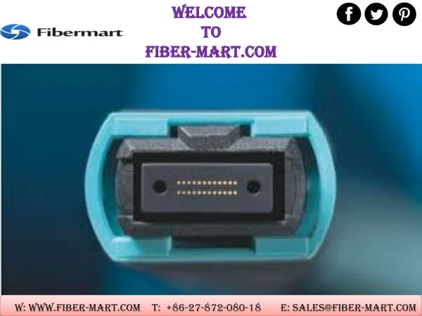
MTRJ connector MTP connector Connectors without “standard” ferrules Flat rectangular “ferrule” for up to 12 fibers per connector. MTRJ is primarily used with Multimode fibers but Singlemode is seen also. MTP is a MPO compatible connector used very often in combination with ribbon fibers respectively where high packing density is required.
Old connectors used for LAN applications • FDDI connectors • FDDI/ST adapters • FDDI/FDDI adapters • ESCON connectors (IBM applications) • ESCON/ST adapters • ESCON/ESCON adapters • FC/PC connectors • FC/FC adapters • FC/ST adapters • SMA connectors • SM/SMA adapters
Thank you Piotr Turowicz Poznan Supercomputing and Networking Center piotrek@man.poznan.pl Training Session http://www.porta-optica.org
References Reichle & De-Massari