Download
1 / 11
110 likes | 267 Views
Chapter 5a: Single-Cycle CPU DataPath. Building A CPU. We’ve built a small ALU Add, Subtract, SLT, And, Or Could figure out Multiply and Divide. What about the rest How do we deal with memory and registers? What about control operations (branches)? How do we interpret instructions?.

E N D
Chapter 5a: Single-Cycle CPU DataPath
Building A CPU • We’ve built a small ALU • Add, Subtract, SLT, And, Or • Could figure out Multiply and Divide... • What about the rest • How do we deal with memory and registers? • What about control operations (branches)? • How do we interpret instructions? • The whole thing... • A CPU’s datapath deals with moving data around • A CPU’s control manages the data 5.1
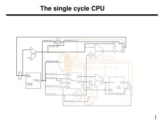
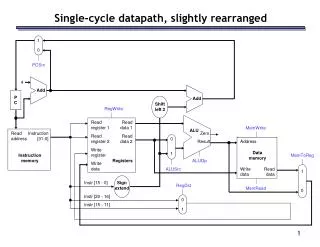
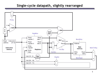
Read reg. num A Read address Read reg data A Data Memory Read reg. num B Read address PC Read data Registers Instruction [31-0] Write address Result Write reg num InstructionMemory Read reg dataB Write data Write reg data ALU Computes on: R-type: 2 registers I-type: Register and data Datapath Overview Current Instruction: PC Instructions: R-type: 3 registers I-type: 2 registers, Data Memory: Address from ALU Data to/from regs Data to write intodest. register from: ALU or Memory 5.1
Instruction Datapath Instructions will be held in the instruction memory The instruction to fetch is at the location specified by the PC Instr. = M[PC] Add Read address PC Instruction InstructionMemory 4 • After we fetch one instruction, the PC must be incremented to the next instruction • All instructions are 4 bytes • PC = PC + 4 Note: Regular instruction width (32 for MIPS) makes this easy 5.2
Instruction Registers R-type Instruction Datapath Read reg. num A Read reg num A Read reg data A Read reg num B Zero Result Write reg num ALU Read reg data B • R-type Instructions have three registers • Two read (Rs, Rt) to provide data to the ALU • One write (Rd) to receive data from the ALU Write reg data • We’ll need to specify the operation to the ALU (later...) • We might be interested if the result of the ALU is zero (later...) 5.2
Data Memory Instruction Zero Registers Result Read reg. num A Read reg num A Read reg data A Read reg num B 16 32 signextend Write reg num Read reg data B Write reg data Memory Operations Read address Read data Write address Write data • Memory operations first need to compute the effective address • LW $t1, 450($s3) # E.A. = 450 + $s3 • Add together one register and 16 bits of immediate data • Immediate data needs to be converted from 16-bit to 32-bit • Memory then performs load or store using destination register 5.2
PC + 4 Result Add Sh.Left2 Registers Read reg. num A Read reg num A Read reg data A Read reg num B Zero Result Write reg num Read reg data B Write reg data 16 32 signextend Branches • Branches conditionally change the next instruction • BEQ $2, $1, 42 • The offset is specified as the number of words to be added to the next instruction (PC+4) Instruction To controllogic • Take offset, multiply by 4 • Shift left two • Add this to PC+4 (from PC logic) offset • Control logic has to decide if the branch is taken • Uses ‘zero’ output of ALU 5.2
Read reg. num A Read reg num A Read address Read reg data A Data Memory Read reg num B Instruction Registers Zero Read data 0 1 Write address Result Write reg num Read reg data B 0 1 Write data Write reg data 16 32 signextend Integrating the R-types and Memory MemoryDatapath • R-types and Load/Stores are similar in many respects • Differences: • 2nd ALU source: R-types use register, I-types use Immediate • Write Data: R-types use ALU result, I-types use memory • Mux the conflicting datapaths together • Punt on the control logic for now 5.3
4 Result Registers Add Read reg. num A Read reg num A Read address Read reg data A Data Memory Read reg num B Read address PC Zero Read data 1 Instruction [31-0] Write address Result Write reg num InstructionMemory 0 Read reg data B 0 Write data Write reg data 1 16 32 signextend Adding the instruction memory Simply add the instruction memoryand PC to the beginning of the datapath. Separate Instruction and Data memories are needed in order to allowthe entire datapath to complete its job in a single clock cycle. 5.3
Registers 0 4 Read reg. num A Read reg num A Result 1 Read address Read reg data A Result Data Memory Add Read reg num B Sh.Left2 Add Zero Read data 1 Write address Result Write reg num 0 Read reg data B 0 Write data Write reg data 1 Read address PC Instruction [31-0] InstructionMemory 16 32 signextend Adding the Branch Datapath Now we have the datapath for R-type, I-type, and branch instructions. On to the control logic! 5.3
When does everything happen? 0 4 Result 1 clk Add Result Sh.Left2 Add Single-Cycle Design Read reg. num A Read reg num A Read address Read reg data A Data Memory Read reg num B Read address PC Zero Read data 1 Registers Instruction [31-0] Write address Result Write reg num InstructionMemory 0 0 Read reg data B Write data Write reg data 1 clk clk 16 32 signextend Combinational Logic:Just does it! Outputs are always just a function of its inputs (with some delay) Registers: Written at the end of the clock cycle. (Rising edge triggered). 5.3