Download
1 / 14
140 likes | 152 Views
Input > Process > Output. Input >Process >Output. Switch Sensor Keypad Key switch Button. BRAIN CIRCUIT Microcontroller Processor Computer. Audio Display Motor Printer Power. An Automatic Sprinkler System.

E N D
Input >Process >Output • Switch • Sensor • Keypad • Key switch • Button • BRAIN • CIRCUIT • Microcontroller • Processor • Computer Audio Display Motor Printer Power
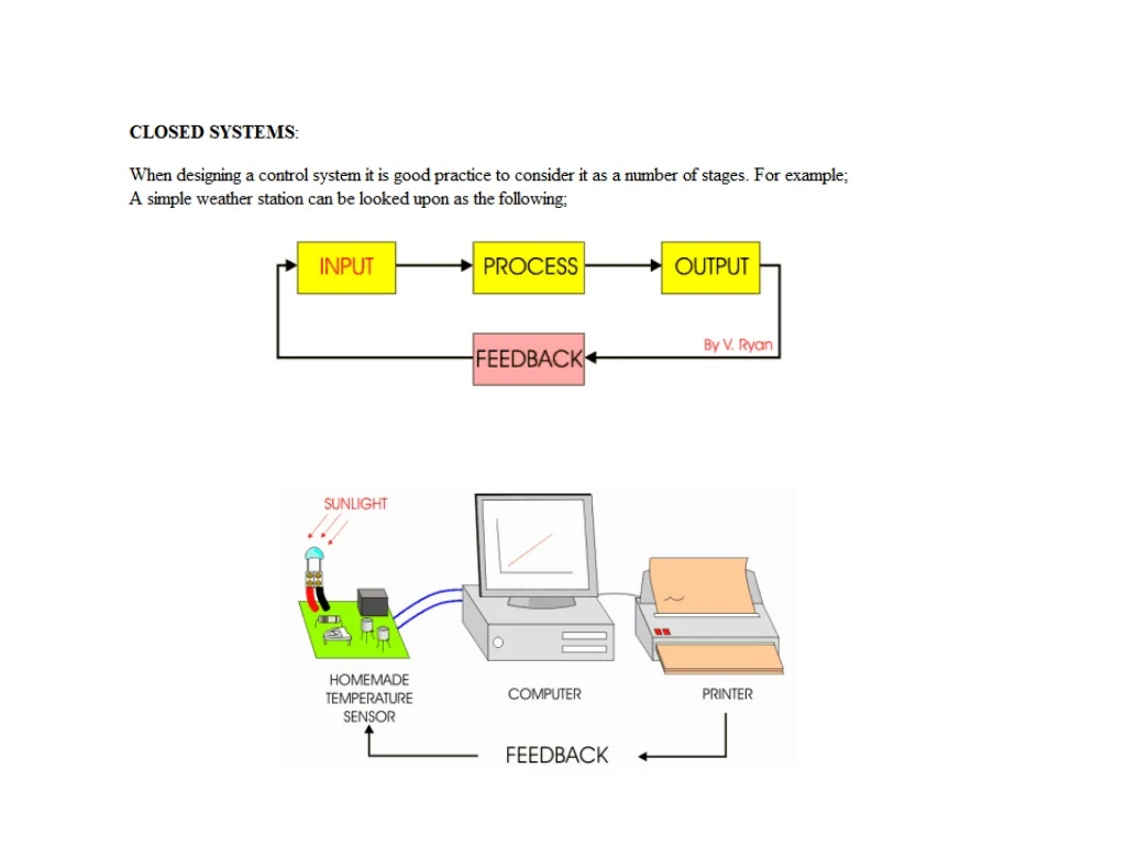
An Automatic Sprinkler System • An automatic water sprinkler system has been ordered by a farmer. The system must have sensors that detect dry weather and turn on water sprinklers to water valuable crops.The company manufacturing the system have decided that a starting point is to think in terms of INPUT -PROCESS - OUTPUT and also include FEEDBACK.
Digital and Logic Gates • Most modern electronic devices such as mobile telephones and computers depend on digital electronics. In fact, most electronics about the home and in industry depend on digital electronics to work. Digital electronics normally based on ‘logic circuits’. These circuits depend on pulses of electricity to make the circuit work. For instance, if current is present - this is represented as ‘1’. If current is not present, this is represented as ‘0’. Digital electronics is based on a series of 1s and 0s.
Logic Gates • LOGIC circuits are normally composed of ‘gates’. A combination of gates make up a circuit and some digital circuits can be extremely complex. It is the logic gates that produce pulses of electrical current (1s and 0s). At school level, digital logic circuits are relatively simple.
AND GATES The simplified AND gate shown above has two inputs, switch Aand switch B. The bulb Q will only light if both switches are closed. This will allow current to flow through the bulb, illuminating the filament.
OR GATES The simplified OR gate shown above has two inputs, switch A and switch B. The bulb Q will light if either switch A or B are closed. This will allow current to flow through the bulb, illuminating the filament.