Download
1 / 43
2.02k likes | 5.62k Views
Heat Exchangers. Chapter 11 Section 11.5. Lecture 17. 4. Effectiveness – NTU Method. Fluid Heat Capacity Rates. New Definitions. Effectiveness – NTU Method. New Definitions. Effectiveness:. N umber of T ransfer U nits:. Effectiveness – NTU Method. For Parallel Flow with C min = C h.

E N D
Heat Exchangers Chapter 11 Section 11.5 Lecture 17
4. Effectiveness – NTU Method Fluid Heat Capacity Rates New Definitions
Effectiveness – NTU Method New Definitions Effectiveness: Number of Transfer Units:
Effectiveness – NTU Method For Parallel Flow with Cmin = Ch
Effectiveness – NTU Method For Parallel Flow with Cmin = Ch
Effectiveness – NTU Method For Counterflow with Cr = Cmin/Cmax
Effectiveness – NTU Method For Counterflow with Cr = Cmin/Cmax
Effectiveness – NTU Method Graphical Representations of Equations in Tables 11.3 & 11.4
5. Methodology for Heat Exchanger Calculation • Heat Exchanger Design -- LOG-Mean Known: Fluid flow rates and Ts Find: Heat exchanger size (Area) • Heat Exchanger Performance Calculation Known: Heat Exchanger Size Find: Heat transfer rate and fluid outlet Ts ε-NTU method is useful for performance calculation
LOG-Mean Method • Calculate unknown fluid T from energy balance; • Calculate Tlm or Tlm,CF; • Calculate P and R, find F value; • Calculate q from energy balance equation; • Determine A from q/(UF Tlm,CF)
Multipass and Cross-flow Heat Exchanger F for different flow arrangements can be found in figures 11S.1-11S.4
Effectiveness – NTU Method • Calculate Ch and Cc, determine Cmin/Cmax; • Calculate NTU from UA/Cmin,find ε; • Calculate q max = Cmin* (Th,i-Tc,i); • Calculate q = ε* q max; • Determine unknown fluid outlet Ts.
Effectiveness – NTU Method • Calculate Ch and Cc, determine Cmin/Cmax; • Calculate q max ; • Calculate q and ε; • Get NTU from the chart or equation; • Determine A from NTU.
Effectiveness – NTU Method For Counterflow with Cr = Cmin/Cmax
Effectiveness – NTU Method For Counterflow with Cr = Cmin/Cmax
Example 11.3 Hot exhaust gases, which enter a finned-tube, cross-flow heat exchanger at 300 C and leave at 100 C, are used to heat pressurized water at a flow rate of 1 kg/s from 35 to 125 C. The exhaust gas specific heat is approximately 1000 J/kgK, and the overall transfer coefficient based on the gas-side surface area is Uh = 100 W/m2K. Determine the required gas-side surface area Ah using both NTU and log-mean methods.
Example 11.3 Known:Hot and cold fluid inlet and outlet Ts, cold fluid flow rates, and hot fluid side overall heat transfer coefficient for a cross-flow heat exchanger Find: Required hot fluid surface area Schematic:
Example 11.3 Assumptions: Negligible heat loss to environment Negligible kinetic and potential energy changes Constant properties Properties: For water, find cpvalue from Table A.6 For exhaust gases, cp=1000 J/kgK is given
Example 11.3 Analysis: NTU Method 1. Calculate Cmin and Cmax, but is unknown
Example 11.3 Ch was obtained from energy balance equations 2. Calculate q max 3. Calculate q and ε
Example 11.3 4. Find NTU from the chart (ε=0.75, Cr=0.45) Figure 11.18, NTU=2.1 5. Find Ah from NTU
Example 11.3 Log-Mean Method 1. Calculate T lm,CF = 111 C 2. Calculate P and R, find F from Fig. 11S.2 P=(to-ti)/(Ti-ti)=0.34, R =(Ti-To)/(to-ti)=2.22 F ≈ 0.87
Example 11.3 3. Calculate Ah
Example 11.4 Consider Example 11.3, the overall transfer coefficient is Uh = 100 W/m2K and area of 40 m2. The water flow rate and inlet temperature remain at 1 kg/s and 35 C. However, a change in operating conditions for hot gas generator causes the gases to now enter the heat exchanger with a flow rate of 1.5 kg/s and a temperature of 250C. What is the rate of heat transfer by the exchanger, and what are the gas and water outlet temperatures?
Example 11.4 Known:Hot and cold fluid inlet conditions for a finned-tube cross-flow heat exchanger of known surface area and overall heat transfer coefficient. Find: Heat transfer rate and fluid outlet Ts. Schematic:
Example 11.4 Assumptions: Negligible heat loss to environment Negligible kinetic and potential energy changes Constant properties Properties: For water, find cpvalue from Table A.6 For exhaust gases, cp=1000 J/kgK is given
Example 11.4 Analysis: NTU Method 1. Calculate Cmin and Cmax,
Example 11.4 2. Calculate NTU and find ε Find ε to be 0.82 from Figure 11.14 3. Calculate qmax
Example 11.4 4. Calculate q q = qmax * ε =2.65x10⁵ W 5. Calculate Th,o and Tc,o
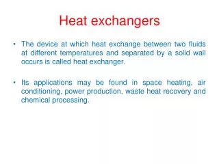
Example 11.5 The condenser of a large steam power plant is a heat exchanger in which steam is condensed to liquid water. Assume the condenser to be a shell-tube heat exchanger consisting of a single shell an 30,000 tubes, each executing two passes. The tubes are of thin wall construction with D=25 mm, and steam condenses on their outer surface with an associated convection coefficient of ho=11,000 W/m2K.
Example 11.5 The heat transfer rate that must be effected by the exchanger is q=2x10⁹W, and this is accomplished by passing cooling water through the tubes at a rate of 3x10⁴ kg/s (the flow rate per tube is therefore 1 kg/s). The water enters at 20 C, while the steam condenses at 50 C. What is the temperature of the cooling water emerging from the condenser? What is the required tube length L per pass?
Example 11.5 Known:Heat exchanger of a single shell and double tube passes with 30,000 tubes Find: Outlet T of cooling water, Tube length per pass to achieve the required heat transfer. Schematic:
Example 11.5 Assumptions: Negligible heat loss to environment Negligible kinetic and potential energy changes Constant properties Fully developed conditions for internal flow Negligible thermal resistance through the tube wall and fouling Properties: For water, find cp, μ and k, Pr values from Table A.6 Assume the average cooling water temperature at 300K
Example 11.5 Analysis: • Calculate Tc,o from energy balance 2. Heat exchanger design calculation using LMTD or NTU method where A = N*2L*D, U=(1/hi+1/ho) -1
Example 11.5 3. Estimate hi frominternal flow correlations • Calculate U = (1/hi+1/ho)-1 = 4478 W/m2K • Calculate Tlm,CF hi= 7552 W/m2K
Example 11.5 6. Calculate L F was determined from Fig. 11S.1, P=0.53, R=0, F=1
Example 11.5 7. NTU method Ch=Cmax = ,
Example 11.5 7. From Figure 11.12, we get NTU =0.75 (Cr=0, and =0.53) NTU = UA/Cmin A=N2DL, U=4478 W/m2K L = NTU * Cmin /(2*U*N**D) = 4.66 m