Download

1 / 30
300 likes | 457 Views
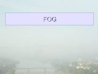
Fog Monitor Overview. Theory and Method Localization Customizing Your Monitoring Area Customizing Your Monitor Thresholds The Fog Monitor Customizing Your Display Thresholds The Fog Monitor Display. Fog Monitor Overview Theory and Method. separate presentation by Qin Zeng.

E N D
Fog Monitor Overview • Theory and Method • Localization • Customizing Your Monitoring Area • Customizing Your Monitor Thresholds • The Fog Monitor • Customizing Your Display Thresholds • The Fog Monitor Display
Fog Monitor OverviewTheory and Method separate presentation by Qin Zeng
Supporting theory Fog monitoring is a kind of object-oriented processing All we have to know is how to describe a fog object: its properties and its behaviors Spectral feature of fog in multiple satellite channels 1. Scattering radiation feature (Daytime) (a) VIS Channel (b) 10.7 (3.9) μm Channel 2. Emitting radiation feature (Nighttime) (a) 3.9 μm Channel (b) 10.7 μm Channel Kinematic feature of fog properties behaviors
Particle/channel Fog stratus Other cloud Long IR Short IR Vis size vs wavelength 1~10 μm 5~6 μm >10 μm 10.7 μm 3.9 μm 0.4-0.7 μm According to Mie scattering theory: In the VIS channel, reflectivity mainly is related to the depth of the cloud/fog. In channel 3.9µm, fog/stratus has maximum scatter rate with its size equivalent to 3.9 µm. Scattering/Reflecting Radiation(1) [1] • Comments: • Here two differences can be used to distinguish fog and cloud: 1) VIS difference; 2) 3.9 µm IR difference. • The fog region in satellite image should be smooth, edge-clear®ular. • Snow cover and sea ice are bad reflectors in channel 3.9 µm, while fog and stratus are good.
Scattering/Reflecting Radiation(2)[12] Data Normalization of the VIS satellite data
Scattering/Reflecting Radiation(3) Normalization with fine tuning
Scattering/Reflecting Radiation(4) [2][13][14] Assumed that all objects are black bodies: so TBemit3.9 = TB11 = Treal , and according to the Planck radiation law, This is how reflective product of RAMSDIS ONLINE is generated . Because of the assumption of black body and TBemit3.9 = TB11 , it is an approximated reflective product and it does not take the angular correction into consideration So in our algorithms, it is not adopted for fog detection but for sea ice/snow cover exclusion. http://www.cira.colostate.edu/RAMM/Rmsdsol/main.html http://www.nrlmry.navy.mil/~turk/intro.html Allen, R.C., P.A. Durkee, and C.H. Wash, 1994: Snow-cloud discrimination with multispectral satellite images. J. Appl. Meteor
Channel VIS (0.4 - 0.7μm) 3.9 μm IR 10.7 μm IR Radiation received by satellite Scattering radiation1 Emitting radiation0 Scattering radiation Emitting radiation ( Mix together) Scattering radiation0 Emitting radiation1 Emitting Radiation(1)[2] 0 means “can be ignored” 1 means “major” Without the presence of sun light, in fog region, a positive value with [10.7 μm channel - 3.9 μm channel]. This difference is caused by the emissivity difference of fog between 10.7 um and 3.9 μm. Above will be good only during the night time: Other water/ice clouds like AC/AS also look similar to Fog in fog product [7]. But in 10.7 μm channel , the brightness temperature of fog is higher than that of higher water/ice cloud (AC/AS). This can in a degree help distinguish them.
Emitting Radiation(2) [2][3] R(satellite)= R(ground) - R(absorbed) + R(cloud) Different emissivities of different cloud types Absorptivity is related to emissivity and the depth of the cloud/fog Planck radiation law Thin cloud (night) : TB(10.7 μm ) - TB(3.9 μm ) < 0 Thick cloud (night) : TB(10.7 μm ) - TB(3.9 μm ) ~ 0 Fog (night) : TB(10.7 μm ) - TB(3.9 μm ) > 0 ice cloud (night) : TB(10.7 μm ) - TB(3.9 μm ) < 0 Water/ice cloud (night) : TB(10.7 μm ) - TB(3.9 μm ) > 0 Comment: So fog product should be checked to eliminate other higher water/ice cloud (AC/AS) by using TB derived from 10.7 μm channel. Sea Fog Discrimination Chart from Gary Elrod
Nighttime use 3.9 and 10.7 um infra-red images to produce night time fog product. Apply feature extraction to identify fog area based on night time fog product threshold SAFESEAS Fog Monitor • process only those parts of the images that cover the monitoring area. Daytime • use the visible image • Based on thresholds, apply feature extraction algorithm to identify fog areas. • apply smoothness filter to eliminate noise. (optional) • Apply a filter to eliminate snow/ice (optional) Twilight No Detection • Filter out high cloud using channel 10.7 um • Apply a filter to eliminate very tiny size area as noise. (optional) • Apply a filter to eliminate edge-irregular detected area (Optional)
SAFESEAS Fog Monitor Smoothness Definition: Smoothness = (1- deviation/mean) * 100% X denotes the gray value at the VIS pixel and n is the number of pixels
Limitations (1) • When the sky is overcast with high level (thick) cloud, fog can not be seen through by satellite. • During the transition of daytime and nighttime, neither VIS product nor fog product is good. And twilight is exactly the time when fog mostly affects marine interests. • Lack of observations in marine zones causes problem for verification • No effective approach to distinguish fog from stratus just using satellite data
Limitations (2)Data normalization At very low solar elevation, in the clear air region , there will still be small brightness values. After normalization, they will be enhanced to look like fog areas and will be detected by the Fog Monitoring Processor.
Limitations (3) Radiation from the ground goes through thin cirrus/high cloud ,which makes cirrus look like fog in VIS
Limitations (3) (continue) [14] Use fractal dimension to try to reduce the detection of the irregular area This is still not a good solution but supplied as an optional filter for user FD = 2ln(P/4)/ln(A) P= perimeter A= Area • Count the outside edges of the grid boxes as the perimeter • Amount of the grid boxes as the area.
Limitations (3) (continue) After Before Application of Fractal Dimension to filter out irregular area
References • [1] Liu Jian, Xu Jianmin, Fang Zongyi Analysis of the particle sizes at the top of cloud and fog with NOAA/AVHRR data Quarterly Journal of Meteorology • [2] http://www.cira.colostate.edu/ramm/visit/fog.html fog product tutorial • [3] http://meted.ucar.edu/topics_fog.php Fog/stratus tutorials • [4] Chen Weimin, Satellite Meteorology (Chinese version) Beijing Meteorological publishing house • [5] Ellrod G P. Advances in Detection and Analysis of Fog at night Using Advanced Very High Resolution Radiometer(AVHRR) Imagery [J] Meteo. Magazine • [6] http://meted.ucar.edu/topics_satellite.php satellite products on METED • [7] http://meted.ucar.edu/satmet/goeschan/ GOES channel selection on METED • [8] http://www.ssd.noaa.gov/ satellite service division homepage • [9] http://aviationweather.gov/awc/aviation_weather_center.html Aviation Weather Center • [10] http://www.cira.colostate.edu/ Cooperative Institute for Research in the Atmosphere, Colorado State University • [11] http://www.nrlmry.navy.mil/ Naval Research Laboratory Monterey • [12] ALBERS S. 1992: Photometric correction of GOES visible satellite images. Preprints, Sixth conf. on Satellite Meteorology and Oceanography, Atlanta, GA, Amer. Meteor. Soc., 223-225. • [13] Allen, R.C., P.A. Durkee, and C.H. Wash, 1994: Snow-cloud discrimination with multispectral satellite images. J. Appl. Meteor • [14] Olsen, E.R., R.D. Ramsey and D.S.Winn. 1993. A modified fractal dimension as a measure of landscape diversity.Photogram. Eng. Remote Sens. 59: 1517-1520 • [15] http://www.cira.colostate.edu/RAMM/Rmsdsol/main.html RAMSDIS ONLINE
Fog Monitor OverviewKey Terms • Area of Responsibility An office’s area of responsibility (AOR) will consist of all the zones and counties for which it normally has the responsibility of issuing forecasts, watches, and warnings. • Monitoring Area An office’s monitoring area (MA) will consist of its AOR plus the AOR of each adjacent office. • Channel 2 Channel 2 refers to the 3.9 micrometer infra-red satellite image. • Channel 4 Channel 4 refers to the 10.7 micrometer infra-red satellite image. • Fog Product The fog product is the image derived by subtracting 10.7 micrometer image brightness temperatures from 3.9 micrometer image brightness temperatures.
Fog Monitor OverviewLocalization • will determine the default MA. * which zones and counties are included in the MA. * (OB-6) which fixed stations are in the MA. * (OB-6) in which zone/county is each fixed station located. For the alpha test, the default MA will be based on the same “shape” files used for OB-4 SAFESEAS. It is the responsibility of each office to make sure its systems have the current versions of these files before localization is run. • will generate the “dummy” fog threat image to display for incomplete image sets. • will generate the default (factory setting) monitor thresholds. • (OB-6) will generate the default (factory setting) display thresholds.
Fog Monitor OverviewCustomizing your Monitoring Area The Fog Monitor will provide a GUI for customizing the MA. Specifically, the office will be able to: • add and delete zones and counties. • (OB-6) add and delete fixed stations. • (OB-6) customize the association of fixed stations with zones and counties, that is, which stations are monitored to determine each zone’s / county’s threat level.
Fog Monitor OverviewCustomizing Your Monitor Thresholds The Fog Monitor will provide a GUI that will enable offices to customize the range of: • normalized brightness values that should be considered fog in visible images. • temperature differences that should be considered fog in fog product images.
Fog Monitor OverviewCustomizing Your Monitor Thresholds (continued) The customization GUI will also allow offices to enable/disable filters in the fog recognition algorithm: • in channel 2 images, each pixel colder than a customizable threshold temperature should be considered snow/ice. • in channel 2 images, each pixel having a brightness temperature colder than a customizable threshold temperature should be considered cloud. • in channel 2 images, each pixel having a brightness temperature warmer than a customizable threshold temperature should be considered ground or water surface. • in visible images, a group of contiguous pixels having a brightness variation greater than a customizable threshold cannot be considered fog. • in visible images, a group of contiguous pixels having fewer than a customizable number of pixels cannot be considered fog. • a pixel within a configurable number of degrees from the terminator should not be monitored.
Fog Monitor OverviewCustomizing Your Monitor Thresholds (concluded) In OB-6, a GUI will also be provided that will enable offices to customize the thresholds used for monitoring point observations (METARs, C-MAN reports, ship reports, buoy reports, and mesonet reports) for fog. We will “negotiate” details for this tomorrow!
Fog Monitor OverviewThe Fog Monitor The fog monitor will be a persistent background process, much like the SAFESEAS, SCAN, and FFMP processors. The alpha test version will monitor: • visible imagery at those times and in those places that the sun is sufficiently above the horizon; • the fog product at those times and in those places that the sun is sufficiently below the horizon. In all cases, channel 2 images are used for certain kinds of filtering (unless the office has disabled the filters). The OB-6 fog monitor will also monitor point observations. The details of this will be “negotiated” tomorrow. The fog monitor will determine a fog threat level for each zone/county in the MA, and an overall fog threat level for the entire MA. The threat level is the most severe of all the individual pixel (OB-6: and point observation fog) threat levels for the past two hours. The fog monitor generates a fog threat level image and a zone fog threat file for use by the Fog Monitor display. Finally, the Fog Monitor threat level indicator and the Fog Monitor display are signaled to update themselves.
Fog Monitor OverviewThe Fog Monitor Display • the Fog Monitor fog threat level image: * black = this location is not within the MA. * gray = insufficient data is available for determining the fog threat level for this location. * green = there probably is not fog at this location. * yellow = there may be fog at this location. * red = there probably is fog at this location. • (OB-6) the Fog Monitor station plot: * only reports from within the MA are plotted. * variables to be plotted will be “negotiated” tomorrow.
Fog Monitor OverviewThe Fog Monitor Display (concluded) • the alpha test Fog Monitor zone fog threat table: * two columns: zone ID and fog threat level (color). * click column header to sort by that column. • the OB-6 Fog Monitor zone/station fog threat tables and trends: * except for variables, same as SAFESEAS. * variables to be included will be “negotiated” tomorrow.