Download

1 / 23
230 likes | 402 Views
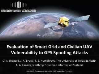
Evaluation of Smart Grid and Civilian UAV Vulnerability to GPS Spoofing Attacks. D. P. Shepard , J. A. Bhatti , T. E. Humphreys, The University of Texas at Austin A. A. Fansler , Northrop Grumman Information Systems ION GNSS Conference, Nashville, TN | September 21, 2012. Outline.

E N D
Evaluation of Smart Grid and Civilian UAV Vulnerability to GPS Spoofing Attacks D. P. Shepard, J. A. Bhatti, T. E. Humphreys, The University of Texas at Austin A. A. Fansler, Northrop Grumman Information Systems ION GNSS Conference, Nashville, TN | September 21, 2012
Outline • GPS Spoofing Attack • Spoofing Exercises • PMUs • Civilian UAV
Civil GPS Spoofing • Goal: influence a specific GPS receiver’s Position-Velocity-Time (PVT) solution • The proximity spoofing attack looks like this • The spoofer was recently modified to allow spoofing at a distance
PMU Spoofing Exercise Goals • Demonstrate that the IEEE C37.118 Standard “Synchrophasors for Power Systems” can be broken by a spoofer • Defines required accuracy as <1% Total Vector Error (TVE), where • Violated once the timing has been altered by 26.5 µs (0.573o phase angle error) • Show that spoofing can affect PMU-based control schemes
PMU Spoofing Exercise Results • Phase angle difference should nominally be 0, since the PMUs were in the same room • Points 1-5 on the plot indicate benchmarks in the test • The phase angle difference is greater than 70 degrees after half an hour
Test Results (cont.) • Point 1: Start of the test shows time and phase alignment between PMUs • Left plot shows Pulse-Per-Second output from receivers with the reference in yellow • Right plot shows phase angle from the PMUs with the reference in red
Test Results (cont.) • Point 2: 620 seconds into the test • 2 µs time offset has been introduced • Receiver is considered fully captured at this point • Spoofer-induced time rate begins accelerating
Test Results (cont.) • Point 3: 680 seconds into the test • Spoofer has broken the IEEE C37.118 Standard • A 26.5 µs timing offset and a 0.573 degree phase angle offset have been introduced
Test Results (cont.) • Point 4: 870 seconds into the test • A 400 µs timing offset and a 10 degree phase angle offset have been introduced • Spoofer has reached final induced time rate of 1000 m/s (i.e. 3.33 µs/s)
Test Results (cont.) • Point 5: 1370 seconds into the test • A 2 ms timing offset and a 45 degree phase angle offset have been introduced • Spoofed signals removed • The receiver’s time offset continued to increase anyways
Smart Grid Vulnerability Conclusions • A spoofing attack can cause PMUs to violate the IEEE C37.118 Standard • Large phase angle offsets can be induced in a matter of minutes (>10 degrees) • These effects can have significant impacts on PMU-based power grid control systems • PMUs were created to help prevent blackout events, but spoofing could make them the cause
Civilian UAV Spoofing Exercise Motivation • Iranian claims of UAV capture • Possible jamming of communications link and/or military GPS signals could allow UAV capture through civilian GPS spoofing. • FAA Modernization and Reform Act of 2012 • Requires the government to develop a plan to safely accelerate the integration of civil UAVs into the national airspace by 9/30/2015.
Commandeering a UAV via GPS Spoofing Target UAV Receive Antenna External Reference Clock Spoofed Signals as a “Virtual Tractor Beam” Control Computer Internet or LAN Transmit Antenna GPS Spoofer UAV coordinates from tracking system
Surprises • RAIM was helpful for spoofing: we couldn’t spoof all signals seen by UAV due to our reference antenna placement, but the Hornet Mini’s uBlox receiver rejected observables from authentic signals, presumably via RAIM • Overwhelming power is required for clean capture: A gradual takeover leads to large (50-100 m) multipath-type errors as the authentic and counterfeit signals interact • The UAV’s heavy reliance on altimeter for vertical position was easily overcome by a large vertical GPS velocity
Surprises • Not possible even to station keep with a captured UAV based on visual position estimates: GPS capture breaks flight controller’s feedback loop; now spoofer must play the role formerly assumed by GPS. Implication: An accurate radar or LIDAR system would be required for fine “control” of UAV via spoofing • Compensating for all system and geometric delays to achieve meter-level alignment is challenging but quite possible