Download
1 / 40
490 likes | 1.23k Views
Fieldbus Technology. Presenter: Todd Shadle tshadle@phoenixcon.com Lead Product Marketing Specialist Serial / Process Fieldbus. Outline. What is ‘process’ Fieldbus Overview Layout of Fieldbus Networks General layout Hazardous locations / I.S. Definition of Fieldbus and Technology

E N D
FieldbusTechnology Presenter: Todd Shadle tshadle@phoenixcon.com Lead Product Marketing Specialist Serial / Process Fieldbus
Outline • What is ‘process’ • Fieldbus Overview • Layout of Fieldbus Networks • General layout • Hazardous locations / I.S. • Definition of Fieldbus and Technology • Components • Segment protectors • Power supplies • Cabling & Connection • Hosts (DCS) and instruments
Factory Automation Making things – solids Factory functions Machine Control Material Handling More discrete signals than analog Process Automation Batch / Continuous – fluids Pipes, Tanks, Valves, Pumps Process functions Flow rates Pressure Temperature Levels More analog than discrete Challenges Explosive Possibility of spills (environmental concerns) Toxic / Corrosive Factory Automation / Process Automation
Outline • What is ‘process’ • Fieldbus Overview • Layout of FF network • General layout • Hazardous locations / I.S. • Definition of FF and Technology • Components • Segment protectors • Power supplies • Cabling & Connection • Hosts (DCS) and instruments
ARC Definition of Fieldbusvs. Device Networks Type of Control Process Control Fieldbus Devicebus Logic Control Sensorbus Type of Devices Complex Devices Simple Devices Message Type Bit Byte Block We Will Continue to Live in a Multi-Protocol World
Ethernet Profibus PA HART Fieldbus & Device Network Applicability ATM / FDDI Business FF HSE H2 Profibus FMS Control ControlNet Profibus DP CCLink Interbus Device DeviceNet SDS CAN FF H1 LonWorks WorldFIP Bit-level Sensor I Loop ASI Seriplex Discrete Process
Fieldbus Benefits • Open Automation Infrastructure • Greatly Improved Asset Management • Reduced Wiring Costs ??? • Reduced Process Variability (digital vs analog) • Increased Capacity Utilization • Reduced Maintenance Costs • Reduced Commissioning – auto detection • Reduced Spare Parts Inventory (trending data) • Improved Safety & Regulatory Compliance
Outline • What is ‘process’ • Fieldbus Overview • Layout of FF network • General layouts • Hazardous locations / I.S. • Definition of FF and Technology • Components • Segment protectors • Power supplies • Cabling & Connection • Hosts (DCS) and instruments
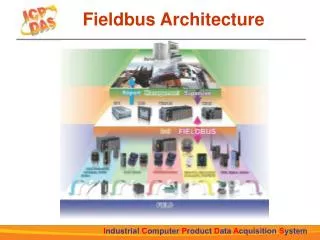
General Layout – FF H1 Segment Control Cabinet Redundant with diode and backup UPS Foundation Fieldbus Bulk power supply Emerson Yokogawa Honeywell Siemens Smar Invensys ABB Host with FF cards “SEGMENT” FF power supply / conditioner T Terminator Transient suppressor Segment protectors Field Field Additional SEGMENTS “SPURS” “TRUNK” Terminator • Devices per segment • <32 protocol supported • <16 host supported • 8-12 installed reality T long distance (up to 1900m total) FF devices FF devices 12| Process Fieldbus |Vogt | Interface | 4/2/2014
General Layout Profibus PA PLC DP Terminator T “SEGMENT” DP/PA Coupler DP/PA Link Field “SPURS” “TRUNK” Terminator T long distance (up to 1900m total) FF devices FF devices 13| Process Fieldbus |Vogt | Interface | 4/2/2014
Outline • What is ‘process’ • Fieldbus Overview • Layout of FF network • General layout • Hazardous locations / I.S. • Definition of FF and Technology • Components • Segment protectors • Power supplies • Cabling & Connection • Hosts (DCS) and instruments
Safe AreaGeneral Purpose Control Cabinet Class 1 Div 2Zone 2
Centralized - NI and IS protection done in the control cabinet Ex – Traditional Solution Safe area General purpose Control Cabinet Junction Box / Segment Protector Voltage and Current limited to the field Class I, Div.2 Zone 2 Power Supply Junction Box / Segment Protector Low Power NI Cond. / Barrier FNICO Fieldbus Nonincendive Concept Class I, Div.1 Zone 1,0 Junction Box / Segment Protector IS Cond. / Barrier FISCO Lower Power Fieldbus Intrinsically Safe Concept IS Cond. / Barrier Entity Junction Box / Segment Protector Lowest Power Classical Calculations
Distributed - NI and IS protection done in the field Ex – High Power Trunk Safe area General purpose Control Cabinet Junction Box / Segment Protector NI Barrier NI Barrier Class I, Div.2 Zone 2 Power Supply Junction Box / Segment Protector Junction Box / Segment Protector Power Supply IS Barrier Zone 1 Junction Box / Segment Protector Energy limiting PER SPUR Class I, Div.1 Zone 0 IS Barrier Junction Box / Segment Protector Higher V = longer cable runs Higher I = maximum # number of instruments per segment, even for IS
Safe AreaGeneral Purpose Control Cabinet Class 1 Div 2Zone 2 Class 1 Div 1Zone 1 Zone 0
Intrinsic Safety Isolators 19| Process Fieldbus |Vogt | Interface | 4/2/2014
Outline • What is ‘process’ • Fieldbus Overview • Layout of FF network • General layouts • Hazardous locations / I.S. • Definition of Fieldbus and Technology • Components • Segment protectors • Power supplies • Cabling & Connection • Hosts (DCS) and instruments 20| Process Fieldbus |Vogt | Interface | 4/2/2014
Technical Basics of Foundation Fieldbus • Bi-directional digital communications protocol used for communication between Foundation Fieldbus devices and the control system • Digital communications and DC-powered network • Increases data to the user for diagnostics and asset management • Consolidates wiring versus standard point-to-point • Provides power and communications over a single shielded twisted pair • FF is more than communications – control in the field via function blocks • Manchester Bi-phase L encoding • Data rate of 31.25 kbps (H1 layer) • Pass token • Devices/Instruments… • Will work between 9 – 32Vdc • 10mA – 20mA avg. • Transmit using current signaling • Receive using voltage signaling
_ _ _ _ + + + + Current – Voltage Signaling 24.5 24 23.5 20mA Cheap-O-scope 5mA 5mA 20mA 10mA 30mA 24VDCPowerand Conditioner FF Device 100 Ω 100 Ω 1µF 5mA 1µF 5mA
Outline • What is ‘process’ • Fieldbus Overview • Layout of FF network • General layout • Hazardous locations / I.S. • Definition of FF and Technology • Components • Segment protectors • Power supplies • Cabling & Connection • Hosts (DCS) and instruments
FIELDBUS SEGMENT PROTECTORS • Junction module provides a ‘star’ connection for end instruments to connect to the bus. • Short circuit protection prevents an instrument failure from disrupting the entire segment.
General Layout – FF H1 Segment Control Cabinet Bulk power supply Host with FF cards Device Fault Short Circuit FF power supply / conditioner T Terminator Transient suppressor Field Terminator T FF devices
General Layout – FF H1 Segment Control Cabinet Bulk power supply Device Fault Example Host with FF cards 6 devices at 15 mA each FF power supply / conditioner Segment protector circuitry limits short T 131 mA 90 mA Terminator 56 mA 15 mA Transient suppressor Field T Terminator FF devices
Device Couplers • Short circuit protection: 15-60mA, fixed / switchable • 2,4,6,8,10,12-spur versions • A device can be removed without disrupting communication • Terminator: built-in, switchable, external, or automatic • LED indication of status • Access points for handheld communicators • Entire approvals range available in most cases… Zone 0-1-2, Div 1-2 • Compatible with FISCO, FNICO, or Entity • Pluggable screw terminals • IP20 DIN mount and IP67 with enclosure options
Device Couplers • Trunk Module • Power from the trunk to TBus • Limits trunk voltage (9..32V) • Low voltage warning < 12V • User configurable shield • External terminator (-ET) installed in trunk-Out terminal
New Couplers • 2-Spur Module • Two nonincendive spur outputs • Ease of wiring in enclosure • Four discrete current-limiting setpoints
Outline • What is ‘process’ • Fieldbus Overview • Layout of FF network • General layout • Hazardous locations / I.S. • Definition of FF and Technology • Components • Segment protectors • Power supplies • Cabling & Connection • Hosts (DCS) and instruments
FOUNDATION FIELDBUS POWER SUPPLIES • FF Power supplies are used to provide power to each segment while allowing for isolation between segments. • An integrated filter prevents the power supply from eliminating, or sinking, the superimposed data on the network.
FF-831 Fieldbus Power Supplies • Single channel isolated and multi channel redundant • versions • 1,2,4,8-segment variations • Alarm contact for indication of failures • Advanced bus diagnostics • Built-in terminators • Input 18-30Vdc • Output 14-30Vdc @ 350-1A load • Non isolated versions also available (“power conditioner”)
Outline • What is ‘process’ • Fieldbus Overview • Layout of FF network • General layout • Hazardous locations / I.S. • Definition of FF and Technology • Components • Segment protectors • Power supplies • Cabling & Connection • Hosts (DCS) and instruments
Fieldbus Cable Types vs. Max. Length Type “A” is Preferred cable type according to IEC/ISA standard for new installations Source: Foundation Fieldbus Wiring and Application Guideline
Cable Connections • Typical Connections are discrete to terminal blocks • Some manufacturers offer over molded 7/8” connectors • Most Instrument manufacturers offer discrete and 7/8” connections
Outline • What is ‘process’ • Fieldbus Overview • Layout of FF network • General layout • Hazardous locations / I.S. • Definition of FF and Technology • Components • Segment protectors • Power supplies • Cabling & Connection • Hosts (DCS) and instruments
ABB Invensys Control Systems Control Systems Magmeters Pressure Transmitter Pressure Transmitter Temperature Transmitter Vortex/Swirl Meters Vortex Flowmeter Mass Flowmeter Emerson Process Solutions Honeywell Control Systems Control Systems Digital Valve Controller Pressure Transmitter FloVue Final Control System Temperature Transmitter Pressure Transmitter Temperature Transmitter Yokogawa Valve PositionerControl Systems Vortex Flowmeters Analytical Equipment Magmeters Valve Positioner Analytical Equipment Temperature Transmitter Coriolis Flowmeters Vortex Flowmeter Pressure Transmitter Major Suppliers & FF-Compatible Products