Download
1 / 19
190 likes | 338 Views
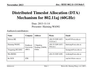
Channel Measurement for IEEE 802.11aj (45 GHz). Date: 2013-4-24. Authors/contributors:. Transmission Scenario Measurement Setup Channel Measurement Results. Outline. Conference room Cubicle room Living room. Transmission Scenarios. Conference Room. Transmission Scenario

E N D
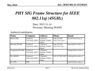
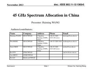
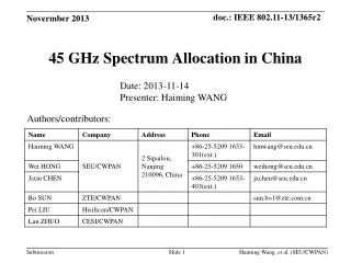
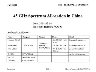
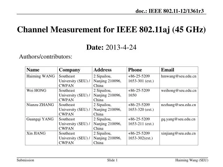
Channel Measurement for IEEE 802.11aj (45 GHz) Date: 2013-4-24 Authors/contributors: Haiming Wang (SEU)
Transmission Scenario • Measurement Setup • Channel Measurement Results Outline Haiming Wang (SEU)
Conference room Cubicle room Living room Transmission Scenarios Haiming Wang (SEU)
Conference Room Haiming Wang (SEU)
Transmission Scenario • Measurement Setup • Channel Measurement Results Outline Haiming Wang (SEU)
Channel Measurement Setup • A PC is used to not only control the rotary table with an RS-232 port but also control the signal generator and network analyzer with LAN ports. • The signal generator transmits CW signal at each frequency, then Rx power and channel frequency response are obtained by the network analyzer. The positions of Tx and Rx antennas and measured data are simultaneously recorded. Haiming Wang (SEU)
Parameters of Q-band Channel Measurement Haiming Wang (SEU)
Type II: Open-ended waveguide (OEW) antenna with 6-dBi gain Antennas for Channel Measurement • Type I: Horn antenna with 23.7-dBi gain H-Plane E-Plane Pattern (dB) Angle (degree) Haiming Wang (SEU)
Power Delay Profile (PDP)of STA-STA Fig. 1 STA-STA Transmission dTR= 3.47 m, hT=hR = 1.04 m, φT =φR = 00, PT= 0 dBm BW: 270 MHz, fc: 45 GHzTx Ant: Type I, Rx Ant: Type I Fig.2 STA-STA Transmission dTR= 3.47 m, hT = hR = 1.04 m, φT= φR = 00 PT= 0 dBm, BW: 270 MHz, fc: 45 GHzTx Ant: Type II; Rx Ant: Type I Haiming Wang (SEU)
Power Delay Profile (PDP) of AP-STA Fig. 1 AP-STA Transmission dTR= 5.59 m, hT = 2.72m , hR = 1.04 m, φT = -150 , φR = 00 BW: 270 MHz, fc: 45 GHzTx Ant: Type I, Rx Ant: Type I Fig.2 AP-STA Transmission dTR= 5.59 m, hT = 2.72m, hR = 1.04 m, φT= -150 , φR = 00 PT= 0 dBm, BW: 270 MHz, fc: 45 GHzTx Ant: Type II; Rx Ant: Type I Haiming Wang (SEU)
Power Angle Profile (PAP) of STA-STA Fig. 1 PAP of STA-STA Transmission dTR= 3.47 m, hT=hR = 1.04 m, φT =φR = 00, PT= 0 dBm BW: 270 MHz, fc: 45 GHzTx Ant: Horn antenna or OEW antenna Rx Ant: Horn antenna • For horn antenna, • For OEW antenna, Haiming Wang (SEU)
Power Angle Profile (PAP) of AP-STA Fig. 1 PAP of STA-STA Transmission hT = 2.7m , hR = 1.3 m, dTR= 5.83 m φT = -150 , φR = 00 PT= 0 dBm BW: 270 MHz, fc: 45 GHzTx Ant: Horn antenna or OEW antenna Rx Ant: Horn antenna • For horn antenna, • For OEW antenna, Haiming Wang (SEU)
More Measurement Positions in a Conf. Room Fig 2. Meas. Positions of AP-STA Fig 1. Meas. Positions of STA-STA Haiming Wang (SEU)
Statistical Parameters TABLE I STA-STA TABLE II AP-STA Haiming Wang (SEU)
Joint AoA and AoD Measurement Setup • A PC is used to not only control two rotary tables with two RS-232 ports but also control the signal generator and the vector network analyzer (VNA) with LAN ports. • The signal generator transmits CW signal at each frequency, then Rx power and channel frequency response are obtained by the network analyzer. The positions and angles of Tx and Rx antennas and measured data are simultaneously recorded. Haiming Wang (SEU)
PAP of STA-STA Transmission Haiming Wang (SEU)
The 45 GHz band channel will be measured in cubicle room and living room, additionally; More measurement data will be obtained, which will be used for statistical channel modeling; Penetration losses for different kinds of walls and blockage objects will also be measured; Some parameters, for example penetration losses, PAP and PDP of multipath will be compared between 45 GHz and 60 GHz bands. Future Works Haiming Wang (SEU)
Revision History Haiming Wang (SEU)
Thank you very much for your attention! Haiming Wang (SEU)