Download
1 / 24
240 likes | 253 Views
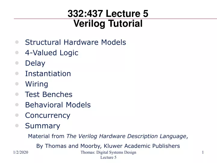
332:437 Lecture 5 Verilog Tutorial. Structural Hardware Models 4-Valued Logic Delay Instantiation Wiring Test Benches Behavioral Models Concurrency Summary. Material from The Verilog Hardware Description Language , By Thomas and Moorby, Kluwer Academic Publishers.

E N D
332:437 Lecture 5Verilog Tutorial • Structural Hardware Models • 4-Valued Logic • Delay • Instantiation • Wiring • Test Benches • Behavioral Models • Concurrency • Summary Material from The Verilog Hardware Description Language, By Thomas and Moorby, Kluwer Academic Publishers Thomas: Digital Systems Design Lecture 5
The Verilog Hardware Description Language Professor Don Thomas Carnegie Mellon University (CMU) thomas@ece.cmu.edu http://www.ece.cmu.edu/~thomas The Verilog Hardware Description Language, Fifth Edition is available from Kluwer Academic Publishers, http://www.wkap.com. Phone: 781-871-6600 This is not one cohesive presentation on Verilog. The slides contained here are collected from different CMU classes at various academic levels. These slides are provided as an alternate aid to learning the language. You may find them helpful. Send bug reports to the above address — there are some! Use or reproduction of the information provided in this file for commercial gain is strictly prohibited. Explicit permission is given for the reproduction and use of this information in an instructional setting. Thomas: Digital Systems Design Lecture 5
f1 a a nsel f f f2 b b sel sel f = a • sel’ + b • sel Representation: Structural Models • Structural models • Are built from gate primitives and/or other modules • They describe the circuit using logic gates — much as you would see in an implementation of a circuit. • Identify: • Gate instances, wire names, delay from a or b to f. • This is a multiplexor — it selects one of n inputs (2 here) and passes it on to the output module MUX (f, a, b, sel); output f; input a, b, sel; and #5 g1 (f1, a, nsel), g2 (f2, b, sel); or #5 g3 (f, f1, f2); not g4 (nsel, sel); endmodule Thomas: Digital Systems Design Lecture 5
Representation: Gate-Level Models • Need to model the gate’s: • Function • Delay • Function • Generally, HDLs have built-in gate-level primitives • Verilog has NAND, NOR, AND, OR, XOR, XNOR, BUF, NOT, and some others • The gates operate on input values producing an output value • Typical Verilog gate instantiation is: and #delay instance-name (out, in1, in2, in3, …); and #5 g1 (f1, a, nsel); “many” optional a comma here let’s you list other instance names and their port lists. Thomas: Digital Systems Design Lecture 5
Four-Valued Logic • Verilog Logic Values • The underlying data representation allows for any bit to have one of four values • 1, 0, x (unknown), z (high impedance) • x — one of: 1, 0, z, or in the state of change • z — the high impedance output of a tri-state gate. • What basis do these have in reality? • 0, 1 … no question • z … A tri-state gate drives either a zero or one on its output…and if it’s not doing that, its output is high impedance (z). Tri-state gates are real devices and z is a real electrical affect. • x … not a real value. There is no real gate that drives an x on to a wire. x is used as a debugging aid. x means the simulator can’t determine the answer and so maybe you should worry! All values in a simulation start as x. • BTW … • Verilog keeps track of more values than these in some situations. Thomas: Digital Systems Design Lecture 5
A B Input B Nand 0 1 x z 0 1 1 1 1 1 1 0 x x x 1 x x x z 1 x x x A 4-valued truth table for a Nand gate with two inputs Input A Four-Valued Logic • Logic with multi-level logic values • Logic with these four values make sense • Nand anything with a 0, and you get a 1. This includes having an x or z on the other input. That’s the nature of the nand gate • Nand two x’s and you get an x — makes sense! • Note: z treated as an x on input. Their rows and columns are the same • If you forget to connect an input … it will be seen as an z. • At the start of simulation, everything is an x. Thomas: Digital Systems Design Lecture 5
Delay • Transportdelay— input to output delay • “nand #35 (f1, a, b, c);” #35 is the transport delay • What if the input changes during that time? • i.e., how wide must an input spike be to affect the output? • Think of the gate as having inertia. — The input change must be present long enough to get the output to change. (That “long enough” time is called inertial delay) • in Verilog, this time is equal to the transport delay a a c b c b pulse too small, no output change — transport delay a c b Thomas: Digital Systems Design Lecture 5
Let’s Build a Wider 2-bit MUX • Build a 2-bit 2:1 MUX • OK, let’s put two 1-bit 2:1 MUXes in the same module with a common select line • What would it look like? a0 f0 b0 a f b a1 f1 b1 sel sel Thomas: Digital Systems Design Lecture 5
Reuse! • Reuse of smaller objects • Can we use the MUX module that we already designed? • A big idea — instantiation • Modules and primitive gates can be instantiated — copied — to many sites in a design • Previously, two ANDs, one OR, and a NOT gate were instantiated into module MUX • Now we instantiate two copies of module MUX into module wideMux module wideMux (f1, f0, a1, a0, b1, b0, sel); input a1, a0, b1, b0, sel; output f1, f0; MUX bit1 (f1, a1, b1, sel), bit0 (f0, a0, b0, sel); endmodule Instantiate two MUX modules, name them, and specify connections (the order is important). Thomas: Digital Systems Design Lecture 5
Instantiation — Copies • Modules and gate primitives are instantiated == copied • Note the word “copies” • The copies (also called instances) share the module (or primitive) definition • If we ever change a module definition, the copies will all change too • However, the internal entities (gate names, internal port names, and other things to come) are all private, separate copies • Don’t think of module instantiations as subroutines that are called • They are copies — there are 2 MUX modules in wideMux with a total of: ______ AND gates, ______ OR gates, ______ NOT gates 4 2 2 Thomas: Digital Systems Design Lecture 5
Why Is This Cool? • In Verilog • “Primitive” gates are predefined (NAND, NOR, …) • Other modules are built by instantiating these gates • Other modules are built by instantiating other modules, … • The design hierarchy of modules is built using instantiation • Bigger modules of useful functionality are defined • You can then design with these bigger modules • You can reuse modules that you’ve already built and tested • You can hide the detail — why show a bunch of gates and their interconnection when you know it’s a mux! • Instantiation & hierarchy control complexity. • No one designs 1M+ random gates — they use hierarchy. • What are the software analogies? Thomas: Digital Systems Design Lecture 5
How to Wire Modules Together • Real designs have many modules and gates module putTogether (); wire w1, w2, w3, w4; bbb lucy (w1, w2, w3, w4); aaa ricky (w3, w2, w1); … what happens when out1 is set to 1? module bbb (i1, i2, o1, clk); input i1, i2, clk; output o1; xor (o1, i2, …); … module aaa (in1, out1, out2); input in1; output out1, out2; … nand #2 (out1, in1, b); nand #6 (out2, in1, b); … Each module has it’s own namespace. Wires connect elements of namespaces. Thomas: Digital Systems Design Lecture 5
Implicit Wires • How come there were no wires declared in some of these modules? • Gate instantiations implicitly declare wires for their outputs. • Allother connections must be explicitly declared as wires — for instance, connections between module ports • Output and input declarations are wires module mux (f, a, b, sel); output f; input a, b, sel; and #5 g1 (f1, a, nsel), g2 (f2, b, sel); or #5 g3 (f, f1, f2); not g4 (nsel, sel); endmodule module putTogether (); wire w1, w2, w3, w4; mux inst1 (w1, w2, w3, w4); aaa duh (w3, w2, w1); … wires explicitly declared wires implicitly declared (f1, f2, nsel) Thomas: Digital Systems Design Lecture 5
How to Build and Test a Module • Construct a “test bench” for your design • Develop your hierarchical system within a module that has input and output ports (called “design” here) • Develop a separate module to generate tests for the module (“test”) • Connect these together within another module (“testbench”) module design (a, b, c); input a, b; output c; … module testbench (); wire l, m, n; design d (l, m, n); test t (l, m); initial begin //monitor and display … module test (q, r); output q, r; initial begin //drive the outputs with signals … Thomas: Digital Systems Design Lecture 5
Another View of This • 3 chunks of Verilog, one for each of: TESTBENCH is the final piece of hardware which connects DESIGN with TEST so the inputs generated go to the thing you want to test... Your hardware called DESIGN Another module, called TEST, to generate interesting inputs Thomas: Digital Systems Design Lecture 5
An Example Module testAdd generated inputs for module halfAdd and displayed changes. Module halfAdd was the design module testAdd (a, b, sum, cOut); input sum, cOut; output a, b; reg a, b; initial begin $monitor ($time,, “a=%b, b=%b, sum=%b, cOut=%b”, a, b, sum, cOut); a = 0; b = 0; #10 b = 1; #10 a = 1; #10 b = 0; #10 $finish; end endmodule module tBench; wire su, co, a, b; halfAdd ad (su, co, a, b); testAdd tb (a, b, su, co); endmodule module halfAdd (sum, cOut, a, b); output sum, cOut; input a, b; xor #2 (sum, a, b); and #2 (cOut, a, b); endmodule Thomas: Digital Systems Design Lecture 5
The Test Module module testAdd(a, b, sum, cOut); input sum, cOut; output a, b; reg a, b; initial begin $monitor ($time,, “a=%b, b=%b, sum=%b, cOut=%b”, a, b, sum, cOut); a = 0; b = 0; #10 b = 1; #10 a = 1; #10 b = 0; #10 $finish; end endmodule • It’s the test generator • $monitor • prints its string when executed. • after that, the string is printed when one of the listed values changes. • only one monitor can be active at any time • prints at end of current simulation time • Function of this tester • at time zero, print values and set a=b=0 • after 10 time units, set b=1 • after another 10, set a=1 • after another 10 set b=0 • then another 10 and finish Thomas: Digital Systems Design Lecture 5
Another Version of a Test Module module testAdd (test, sum, cOut); input sum, cOut; output [1:0] test; reg [1:0] test; initial begin $monitor ($time,, "test=%b, sum=%b, cOut=%b", test, sum, cOut); test = 0; #10 test = test + 1; #10 test = test + 1; #10 test = test + 1; #10 $finish; end endmodule • Multi-bit “thingies” • test is a two-bit register and output • It acts as a two-bit number (counts 00-01-10-11-00…) • Module tBench needs to connect it correctly — mod halfAdd has 1-bit ports. module tBench; wire su, co; wire [1:0] t; halfAdd ad (su, co, t[1], t[0]); testAdd tb (t, su, co); endmodule Connects bit 0 or wire t to this port (b of the module halfAdder) Thomas: Digital Systems Design Lecture 5
Another Version of testAdd module testAdd (test, sum, cOut); input sum, cOut; output [1:0] test; reg [1:0] test; initial begin $monitor ($time,, "test=%b, sum=%b, cOut=%b", test, sum, cOut); for (test = 0; test < 3; test = test + 1) #10; #10 $finish; end endmodule • Other procedural statements • You can use “for”, “while”, “if-then-else” and others here. • This makes it easier to write if you have lots of input bits. module tBench; wire su, co; wire [1:0] t; halfAdd ad (su, co, t[1], t[0]); testAdd tb (t, su, co); endmodule hmm… “<3” … ? Thomas: Digital Systems Design Lecture 5
Structural Vs. Behavioral Models • Structural model • Just specifies primitive gates and wires • i.e., the structure of a logical netlist • You basically know how to do this now. • Behavioral model • More like a procedure in a programming language • Still specify a module in Verilog with inputs and outputs... • ...but inside the module you write code to tell what you want to have happen, NOT what gates to connect to make it happen • i.e., you specify the behavior you want, not the structure to do it • Why use behavioral models • For testbench modules to test structural designs • For high-level specs to drive logic synthesis tools Thomas: Digital Systems Design Lecture 5
How Do Behavioral Models Fit In? module testAdd (a, b, sum, cOut); input sum, cOut; output a, b; reg a, b; initial begin $monitor ($time,, “a=%b, b=%b, sum=%b, cOut=%b”, a, b, sum, cOut); a = 0; b = 0; #10 b = 1; #10 a = 1; #10 b = 0; #10 $finish; end endmodule • How do they work with the event list and scheduler? • Initial (and always) begin executing at time 0 in arbitrary order • They execute until they come to a “#delay” operator • They then suspend, putting themselves in the event list 10 time units in the future (for the case at the right) • At 10 time units in the future, they resume executing where they left off. • Some details omitted • ...more to come Thomas: Digital Systems Design Lecture 5
Concurrent Activity • Do these two evaluations happen at the same time? • Yes and No! • Yes … • They happen at the same simulated (or virtual) time • After all, the time when they occur is 27 • No … • We all know the processor is only doing one thing at any given time • So, which is done first? • That’s undefined. We can’t assume anything except that the order is arbitrary. Eval g2, g3 Yes and No! Thomas: Digital Systems Design Lecture 5
Concurrent Activity • The point is • In the real implementation, all activity will be concurrent • Thus the simulator models the elements of the system as being concurrent in simulated time • The simulator stands on its head trying to do this! • Thus, • Even though the simulator executes each element of the design one at a time … • … we’ll call it concurrent Thomas: Digital Systems Design Lecture 5
Summary • Structural Hardware Models • 4-Valued Logic • Delay • Instantiation • Wiring • Test Benches • Behavioral Models • Concurrency • Summary Thomas: Digital Systems Design Lecture 5