Download
1 / 1
10 likes | 198 Views
GEODYN Orbit Determination of Dawn at Vesta using Image Constraints. Abstract : P41B-1887.

E N D
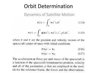
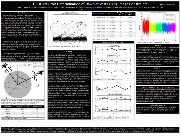
GEODYN Orbit Determination of Dawn at Vesta using Image Constraints Abstract: P41B-1887 Frank J Centinello III1, ErwanMazarico1,2, Maria T Zuber1: 1. Earth, Atmospheric and Planetary Sciences, Massachusetts Institute of Technology, Cambridge, MA, USA; 2. NASA GSFC, Greenbelt, MD, USA CONTACT: fjcent3@mit.edu Introduction The Dawn spacecraft was launched in 2007 to explore the protoplanetsVesta and Ceres to gain insight into planet formation and the early conditions of the solar system [1]. From July 2011 to August 2012, Dawn orbited Vesta, and is now en route to Ceres. GEODYN, the orbit determination (OD) and geodetic parameter estimation software of NASA/Goddard Spaceflight Center, is used to compute the orbit of the spacecraft using radiometric and image constraints. Image constraints are a new data type for GEODYN [2], and are particularly valuable for precise OD in weak, non-uniform gravity environments that are especially affected by non-conservative forces such as solar radiation pressure and spacecraft maneuvers. Any improvements to orbit determination translate directly to improvements in the ability to determine the gravity field of an object and to register datasets to the surface. Image constraints are useful because they can improve the orbit in ways that complement other measurements. They provide position information in the along- and cross-track orbit directions as well as orbital constraints when radiometric observations are unavailable. This work details the first orbit determination efforts with image constraints with GEODYN software. Here, image constraints are defined as they are used in GEODYN. Next, a brief overview of the methodology of this work is provided. Finally, preliminary results of orbit determination of Dawn at Vesta using image constraints in GEODYN are shown here for the first High Altitude Mapping Orbit (HAMO1) phase of the investigation. Analysis Discussion GEODYN successfully uses image constraints for orbit determination. Improvements are seen in overlaps between the GEODYN trajectory and those produced by the navigation team at JPL, nominally in the along- and cross-track directions. Radiometric residual RMS values are larger than the measurement noise. This could be due to mis-modeling of non-conservative forces such as solar radiation pressure. One way to increase sensitivity to solar radiation pressure would be to fit longer orbit arcs to image data. One challenge in using longer orbits is in the estimation of the magnitude of thruster accelerations. Figure 3 shows residual RMS values for radiometric Doppler and range as well as image constraints for each arc in HAMO1. The Doppler RMS varies from 0.9 to 1.4 mm/s and the range RMS varies from 4-7 meters. Image constraint RMS is between 230 and 580 m. Figure 4 shows the difference between overlaps of the orbit computed by GEODYN and that produced by the navigation team at JPL. Here, it can be seen that using image constraints decreases the overlap distance in the along-track orbit direction by 5 to 15 m, and by 20-160 m in the cross- track orbit directions. Figure 5 shows an example of GEODYN minimizing the image constraints. Table 2: Orbit arc time spans. Figure 5: Image constraint values per GEODYN iteration. Results: GEODYN Performance Figure 2: Distribution of landmarks used during HAMO1. Methods In this work, image constraints are defined as the distance between two line-of-sight vectors from the spacecraft to a landmark on the surface of a body (see Figure 1). The vectors P1 and P2 represent the position of the spacecraft in the Vesta-fixed frame at times t1 and t2. The unit control point vectors v1 and v2 point from the spacecraft frame to the pixel location containing a landmark in images taken at times t1 and t2. Theoretically, the distance, d, is zero. This is not the case, however, due to uncertainties in the spacecraft position, attitude, and camera pointing. GEODYN has been modified to minimize d by updating the spacecraft position and attitude. Landmarks produced as a bi-product of the creation of a shape model of Vesta [3, 4] are used to create control point vectors. Over 150,000 landmarks on Vesta are considered for use to create image constraints. A geographic distribution of landmarks used in this study is shown in Figure 2. During HAMO1, the landmark distribution is skewed toward the south pole since the northern latitudes were not illuminated. The pixel locations of landmarks in images are used to compute unit control point vectors in the camera frame. They are then rotated from the camera-fixed frame to the spacecraft body-fixed frame [5, 6]. In addition to image constraints, orbits are estimated using 3-way, X-band Doppler and range measurements. Doppler and range measurements carry a measurement noise of 0.1 mm/s and 2 m, respectively. Images have a resolution of 50-150 m/pixel, depending on the spacecraft altitude [7, 8]. GEODYN first computes the trajectory of the spacecraft accounting for the gravitation of the Earth, Moon, Sun and planets, and solar radiation pressure. Next, the radiometric measurements and image constraints described above are used to fit the orbit and estimates of solar radiation pressure, general accelerations, and measurement biases [2]. For this work, orbit arc time spans were chosen to exclude momentum wheel desaturations, during which the spacecraft thrusters are fired. The start and stop times of arcs are shown in Table 2. Arcs were generally 2-3 days long, and 3000 image constraints were applied in each. Figure 3: Measurement residual RMS for each arc. Acknowledgements Plan for Progression and Other Applications Thanks to Frank Lemoine of NASA/Goddard Spaceflight Center, Sami Asmar, Alex Konopliv, Ryan Park, and Carol Raymond at NASA/Jet Propulsion Laboratory, and Robert Gaskell of the Planetary Science Institute. This work demonstrates a new capability with GEODYN that will aid in the geophysical investigation of Vesta and other bodies. Additional improvement will be sought through the integration of longer orbit arcs spanning across momentum wheel desaturations (rather than excluding them). Next, radiometric and image data from all of Dawn’s mission segments at Vesta will be processed. In addition to Dawn, the development of this technique is relevant to other missions such as MESSENGER, LRO and NEAR. Figure 1: An illustration of control point vectors (v1and v2) corresponding to spacecraft positions on two different orbits P1and P2(in the Vesta body-fixed frame), and the corresponding scalar constraint,d. Figure 4: RMS of overlap of GEODYN-computed orbit with that produced by the spacecraft navigation team for each arc. Table 1: Dawn orbit characteristics at Vesta. [1] Russell, C.T. et al., Space Science Reviews, 163, 3–23, 2011. [2] Pavlis, D., GEODYN Operations Manuals, Raytheon ITTS Contractor Report, Lanham, MD, 2006. [3] Gaskell, R.W., et al., Meteoritics & Planetary Science, 43, No. 6, 1049–1061, 2008. [4] Gaskell, R.W., et al., P41A-1576, San Fancisco, CA, presented at Fall Meeting, AGU, December 2011. [5] Sierks, H., et al., Space Science Reviews, 163, 263– 327, 2011. [6] Sierks, H., et al., “FC Standard Data Products and Archive Volume Software Interface Specification,” tech. rep., Max Planck Institute for Solar System Research and the Dawn Science Center, Max-Planck-Strasse 2, 37191 Katlenburg-Lindau, Germany, University of California, Los Angeles, CA 90095-1567, August 2010. [7] Konopliv , A.S., et al., Space Science Reviews, 163, 461–486, 2011. [8] Thomas, V.C., et al., Space Science Reviews, 163, 175–249, 2011.