Download
1 / 37
400 likes | 879 Views
ITER Towards the Construction Y. Shimomura for the ITER International and Participant Teams 23rd Symposium on Fusion Technology Venice, 20-24th September, 2004 Content Technical Preparations for Construction Design Improvements Manufacturing R&D Procurement Specification Writing

E N D
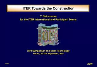
ITER Towards the Construction Y. Shimomura for the ITER International and Participant Teams 23rd Symposium on Fusion Technology Venice, 20-24th September, 2004
Content • Technical Preparations for Construction • Design Improvements • Manufacturing R&D • Procurement Specification Writing • Organisational Preparations for Construction • Risk Management • Configuration Management • Document Management • ITER as a Vehicle for Programme Integration • Diagnostics, Heating, and Test Blankets • Remote Participation in Physics • Broadening the Scope of the “Next Step” • Negotiations Status • Joint Implementation • Resolving the Deadlock
Technical Preparations • Prepare licensing application - close dialogue with potential regulators • Establish technical specifications for long-lead items, i.e. mainly magnets, vacuum vessel, and buildings. • Enhance technical organization to maintain ITER design and prepare for an efficient start of construction. • Develop/implement management tools. • Enhance scientific and technical activities in the Participants (Garching, Naka) International TeamTask Agreement EU Team Regulator JA Team Regulator Blanket Working Group RF Team Diagnostic Working Group China Team International Tokamak Physics Activities US Team S. Korea Team
Design - Main Features Divertor 54 cassettes Central Solenoid Nb3Sn, 6 modules Blanket Module 440 modules Vacuum Vessel 9 sectors Poloidal Field Coil Nb-Ti, 6 Cryostat 24 m high x 28 m dia. Toroidal Field Coil Nb3Sn, 18, wedged Port Plug (IC Heating) 6 heating 3 test blankets 2 limiters/RH rem. diagnostics Fusion Power: 500 MW Plasma Volume: 840 m3 Nominal Plasma Current: 15 MA Typical Temperature: 20 keV Typical Density: 1020 m-3 Torus Cryopump 8 units
Main changes in ITER since July 2001 • Magnets • increased critical current (from ~6 to ~800 A/mm2) • use of stainless steel jacketing in all conductors • outer intercoil structure uses friction joint of welded plates • Vessel/Blanket • support arrangement simplified • nine lower ports • blanket module has FW supported from welded central leg • improved module arrangement around NB ports • improved interlocking of thermal shield • Building/Services • introduction of port cells • relocate gallery equipment - access, e/m loads • incorporate seismic isolation for both potential sites • improve site layout
Port Cell Layout • Second containment barrier moved to port cell door. • Reduced number of operations in irradiated areas.
Vacuum Vessel Support System • VV supported independently of magnets at the lower ports. • Possible to adjust the VV in the pit after welding of the sectors. • Snubbers used to limit the radial movement during earthquake. • Locate parts requiring maintenance outside cryostat. • Simplify assembly.
Results of Magnet R&D • Unexpected loss of cable performance relative to strand. Due to local magnetic loading (70t/m) but not yet fully understood. • Standardise on SS jacket to keep cable in compression and avoid risk of filament fracture. • Modify cable design, increase strand critical current density from 500-700 A/mm2 to 700-800 A/mm2to take advantage of manufacturing improvements since model coils (~10 year old specification). • Strand production tests ongoing with more than 15 vendors worldwide. • Conductor testing underway to quantify magnetic loading degradation effect.
Manufacturing R&D (Problem of one-sided and limited access) Ultrasound of 60 mm plate Photothermal Camera Technique Vacuum vessel weld inspection • PFCI (Poloidal Field Conductor Insert, EU) which will be tested in Naka, Japan, during 2005.. • High Temperature SC Current Lead Test.
Construction Schedule LEGALENTITY LICENSE TO CONSTRUCT TOKAMAK ASSEMBLY STARTS FIRST PLASMA 2004 2005 2006 2007 2008 2009 2010 2011 2012 2013 2014 2015 EXCAVATE Bid TOKAMAK BUILDING Contract PFC BUILDING OTHER BUILDINGS Complete blanket/divertor Complete VV First sector TOKAMAK ASSEMBLY Install CS Install cryostat PFC COMMISSIONING Bid Vendor’s Design MAGNET Contract PFC TFC CS Last TFC Last CS fabrication start Bid VESSEL Contract First sector Last sector
Procurement Specifications • Drafting of detailed technical specifications for long lead items: • Magnets: • strand and conductor • PF and TF coils • Vessel: • main vessel and ports • blanket coolant manifolds • Buildings: • tokamak complex • cryogenic halls used for PF coil winding • service tunnels Task Forces established with PT/IT membership to complete work in necessary detail and with industrial realism • Development of other procurement specifications to cover interfaces with long lead items - resource limited.
Organisational Preparations • Risk Management • Configuration Management • Document Management
Risk Management - The Problem • 90% of items will be provided in kind from the 6 Parties and sharing amongst them has not been optimised especially to minimise risk. • Such an experiment cannot be built without some changes during construction which may affect to a few Paties. • Unlike normal centrally-funded projects, any cost saving or margins actually realised will not be seen by the project for items provided in kind. • The project therefore has no “cushion” for overcost items or failed/delayed deliveries.
Superconducting Strand and Plasma-Facing Components • Risks: • too low production rate; • too low acceptance rate; • too high costs. • Minimisation of risks: • R&D including QA; • Qualification of potential vendors before call for tender; (Trial production and test) • Fixed price contracts with multiple vendors with demonstrated capability; • Staged production and “holding” of cash contingency. • Mitigation of consequences: • Delivery to project of the production prior to where the problem occurred. • Transfer of remaining production to other vendors demonstrating adequate production quality. A solution is needed for funds transfer from the defaulting to the compensating Party.
Tokamak Core Components • Risks: • unacceptable production delays; • inability to reproduce prototype quality in series production; • design changes during early stages of production; • too high costs. • Minimisation of risks: • R&D using full-sized scalable models, and development of detailed fabrication methods and their QA; • Very good initial preparation including detailed specification and planning; • Firm and fixed price contracts for reasonably large packages of work; • If a component is shared between multiple Parties’ vendors, there must be a prime contractor - subcontractor relationship between them; • The direct relationship between the ITER Organisation and the suppliers has to be very good. • Mitigation of consequences: • ITER Organisation must make a large effort to minimise cost impact of changes; • ITER Organisation must try to find compensating cost savings within the contract, or with the same Party on other contracts. • Access may be needed to a general reserve fund as a last resort.
Risk Management - The Strategy • Minimise chances of cost overruns and delivery delays/failure • Large Project R&D. • Manufacturing-related R&D and qualification of potential vendors before construction. • Develop technical specifications and design in detail beforehand. • Centralised tracking of milestones to identify problems early. • Preparation of contingency plans e.g.: • Within multi-party procurements, so the default of one party can be compensated for by another with the minimum of delay. • Staged contracts will be used to check acceptability of prototypes. • Parties need to accept the principle that the defaulting Party must compensate for any extra manufacture by the remaining Parties, and that all Parties may incur extra costs due to any delay caused.
Risk Management - Implications • Project Team needs to be strong enough to be present in the factory so as to recognise and limit such occurrences. • Project Team management has to have the trust of the Parties to be the fair judge of quality and acceptability of deliverables. Parties must safeguard their own and the Project interests by not making stage payments without Project Team concurrence. • The strong presence of the Project Team on the supplier’s premises should allow some difficulties induced by design changes to be absorbed by adapting interfaces with later manufactured items. • The Parties may have to jointly compensate a manufacturing Party for consequent costs exceeding those that Party achieves from other procurements. They may need a contingency for this. • Compensation claims will need to be arbitrated by the ITER Council. • The project must furthermore implement systems which will improve its own efficiency and reduce the risk of errors, e.g.: • Configuration Management • Document Management
Configuration Management Procedures • Technical Coordination Meetings (TCM) • Decides on change proposals (DCRs) • Organises and schedules supporting work and priorities • Design Change Requests (DCR) • Document proposals for changes • Design Work Orders (DWO) • Request CAD effort • Design Work Check (DWC) • Process to check drawing office output • Design Integration/Drawing Office (DIDO) Meetings • Reviews ongoing CAD progress, prioritises new CAD effort allocation, and schedules detailed design reviews Key: Manage change Check conformity Required Actual Documented
Configuration Management Tools - 1 ITER needs “virtual product data management” (VPDM) software for 3D digital mockup, essential for configuration management. clash detection, utility routing, collaborative design with the Participants, need better tools to control the configuration and allocation of the available space. CATIA 4 soon obsolete. Should upgrade to CATIA 5: nearly all procurement models are in one system; be in tune with manufacturers, who have already upgraded, and rehearse conversion processes with other manufacturer’s CAD systems; tailor software systems essential in construction; train operators. All project legacy data in CATIA, so no need to transfer to alternative if the project can obtain a good deal on price. Project anyway has to work out means to deal with other CAD systems, to an extent depending on the level of integration of the system with others, as well as the detail level of the procurement.
Configuration Management Tools - 2 During late 2003 and 2004 ITER IT has implemented Enovia VPM as data manager in conjunction with CATIA V4 and V5. Process well-advanced with a complete switch to production work in CATIA V5 planned for the end of 2004.
Document Management - 1 • Features needed for ITER: • tree/network navigation of linked documents, • approval workflow tracking, • document validity according to circumstances, • electronic signature, • worldwide access to authorised personnel. • good interface with CATIA V4 and V5; • full functionality from multiple platforms (XP, OSX, Linux, Unix); • access security and reliability; • No systems examined had all these features. • Own system developed based on open source toolbox (ZOPE).
Document Management - 2 • Development began in in January 2004. • Almost fully functional system available in July. • Setup of underlying document storage tree structure now being finalised. • Expected to be ready for productive use from ~ October. • So far has required ~ 2 ppy.
ITER as a Vehicle for Programme Integration • Diagnostics*, Heating Systems and Test Blankets • Remote Participation in Physics • Broadening the Scope of the “Next Step” * Friday, A. Costley, “Technological Challenges of ITER Diagnostics”
Heating ECUpper Port EC NB Injector (1)EC H&CD uses 3 upper ports for the power upgrade IC LH RF Layout
(JA) ‘04.5 ‘04.5 (JA) 10 1 10 100 Progress of R&D in NBI - MeV negative ion NB High-Current Density negative ion beam with 1 MeV successfully produced. Beam energy Negative ion current (H-) Negative ion current density (H-) ITER 200 A/m2 1 MeV 40 A MeV accelerator (achieved) 1), 2) 0.8 MeV 0.14 A 102 A/m2 JT-60U N-NBI 0.41 MeV 0.40 MeV 20.4 A (H-) 17.4 A (D-) 150 A/m2 130 A/m2 Note 1) Power supply is limited to max. 1 A. 2) Heat removal of beam dump was limited to 100A/m2 . After the modification, try to produce the required beam (200 A/ m2 ).
Japan 170GHz 110GHz Russia 170GHz 140GHz USA 110GHz 140GHz EU 140GHz 2001-2003 ECRF: Status of Gyrotron Development Progress of Gyrotron R&D JA/170GHz RF/170GHz EU/140GHz JA/110GHz RF/140GHz US/110GHz (170GHz) Test of 170 GHz/1 MW in CW operation (> 400 sec) is in progress.
Test Blanket Modules (TBMs) • Three equatorial ports, shared by several concepts. • Test Blanket Working Group • oversees and coordinates designs of TBMs and machine interfaces;. • promotes co-operation among participants on the associated R&D; • verifies the integration of TBM testing in ITER site safety and environmental evaluations; • develops/proposes coordinated TBM test programs taking into account ITER operation. • Concepts (five multi-Party working design groups established) • water-cooled solid breeder; • helium-cooled solid breeder; • helium-cooled lithium-lead; • self-cooled liquid lithium; • lithium salt. • ITER can prove principle of designs • benchmark fission reactor results; • confirm neutronic and breeding calculations; • tritium control and extraction experiments; • confirm thermohydraulic analysis and basic design principles; • first demonstration of electricity generation from fusion.
Worldwide Experimentation on ITER ITER Site Efficient Use of ITER Involvement of Worldwide Community ITER ITER Remote Experimental Site OP. Permit Exp. Condition Data Exp. Center 1 Test Module Exp. Center 2 Blanket Lab Data Centre Material Lab University Lab Home Example: 3 shift/day on site (night shift for monitoring and support of remote experiment) 1 or 2 shift(s)/day on remote experimental sites Base programme: 2 shift/day operation/experiment on-site
Broadening the Scope of ITER • Suggested initially to resolve ITER siting problem. • Includes: • Remote experimental control centre as focus for interaction with ITER. • Virtual plasma modelling laboratory. • “Satellite” tokamak providing support (and ability to rapidly evaluate new ideas) during ITER construction and operation. • DEMO design team. • DEMO materials test/qualification facility (IFMIF). • Irrespective of role in solving siting, useful to identify the key activities and facilities that will be needed in the immediate future of magnetic confinement development, allowing them to be factored into future planning.
Negotiations • Began in July 2001 with the following aims • draft Joint Implementation Agreement • select ITER construction site • agree how the procurement and costs will be shared • define how the project will be managed • identify the Director General and senior staff. • Provisional agreement on all the above achieved by Dec. 2003. • Deadlocked over choice of construction site. Cadarache or Rokkasho
ITER International Fusion Energy Organisation IIFEO Council Science and Technology Advisory Committee Construction Programme Advisory Committee Auditors Host Country Director-General (DG) DDGs Organisation/Host Relation Organisation Personnel (professionals + support staff) Central Team Staff of DG Supporting Services Support for • Project Management • Computer Network • Technical work • Clerical work etc. Project Manage. Admin. Integration Interface Procure- ment QA. Physics Safety Licensing Host Relation Contract Field Team Field Team Field Team for construction phase Domestic Agency Domestic Agency Domestic Agency Industries and Other Organisations Industries and Other Organisations Industries and Other Organisations
Construction Cost Sharing • EU: TF(0.5), conductors, cassette and outer target, vac.pumps, div. RH, casks (0.5), isotope sep., IC, EC, diag. • JA: TF(0.5), conductors, inner target, blanket RH, EC, diag. • KO: conductors, vessel ports (0.67), blanket (0.2), assembly tools, thermal shield, T storage, AC/DC (0.65), diag. • CN: magnet supports,feeders, correction coils, conductors, blanket (0.2), cryostat, gas injection, casks (0.5), HV substation, AC/DC (0.35), diag. • RF: PF1, conductors, vessel ports (0.33), blanket (0.2), port limiters, flexibles, dome and PFC tests, Discharge circuits, EC, diag. • US: CS(0.5), conductors, blanket (0.1), vac.pumps, pellet inj., vessel/in-vessel cooling, tok exh. proc., IC, EC, diag. • Fund (10%): Feeders, Shielding, viewing, NB RH, Hot cell eq., cryodist., CODAC, installation and test, other sundry items Host provides Buildings and Utilities. Remaining allocation (Flex.) depends on site.
Resolving the Siting Deadlock • Wait - one party may in time recognise importance and benefit of hosting the complementary activities of the broader approach. • The strong support to ITER and fusion, with possibly large resources, can be efficiently used to accelerate integrated magnetic fusion development. • EU and Japan seem ready to fund the broader approach items. • The scientific activities can start immediately in the non-ITER-Host Party.
Conclusions • The ITER Transitional Arrangements are being used at the project technical level to get many things ready that will ease the path once the negotiations are successfully completed: • finalisation of long lead time procurement packages taking account of manufacturing R&D; • experience with tools that are necessary for project and quality control. • • Although negotiations on siting ITER are currently deadlocked, discussions at the necessary level have only been going on since December 2003. Today, it seems best to wait and see if consensus can be achieved by the end of 2004, leading to only 1 year delay in first plasma (now 2015).