IT-606 Embedded Systems (Software)
IT-606 Embedded Systems (Software) S. Ramesh Krithi Ramamritham Kavi Arya KReSIT/ IIT Bombay Models and Tools for Embedded Systems S. Ramesh Organization Model-based Development of Emb. Sys. Review of models of concurrency in programming languages Synchronous Model of concurrency

IT-606 Embedded Systems (Software)
E N D
Presentation Transcript
IT-606Embedded Systems(Software) S. Ramesh Krithi Ramamritham Kavi Arya KReSIT/ IIT Bombay
Organization • Model-based Development of Emb. Sys. • Review of models of concurrency in programming languages • Synchronous Model of concurrency • Introduction to Esterel • Advanced Features of Esterel • Simple case studies using Esterel • Verification • POLIS: A HW-SW co-design tool for ES
Software Development • Software crisis (in the seventies) • Hardware crisis? • Large no. of complex applications • Little experience • Huge gap between requirements and final implementation • Lack of methodologies • Challenge for project managers • Little ways of planning, time-schedule, cost, quality etc.
Software Engineering • Large body of academic and industrial research and experience over 20 years • Emergence of Software Engineering as a discipline • Various Concepts • Structured Programming, Information Hiding, OOP, • Various methodologies • Structured Analysis, Jackson System Development, • Model-based development methodologies is recent outcome • RT- UML, ROOM, SCR, RTSAD, ADARTS . . .
Development Challenges Embedded Systems are quite complex 1.Correct functioning is crucial • safety-critical applications • damage to life, economy can result 2.They are Reactive Systems • Once started run forever. • Termination is a bad behavior. • Compare conventional computing (transformational systems)
Development Challenges 3. Concurrent systems • System and environment run concurrently • multi-functional 4. Real-time systems • not only rt. outputs but at rt. time • imagine a delay of few minutes in pacemaker system
Development Challenges 5. Stringent resource constraints • compact systems • simple processors • limited memory • quick response • good throughput • low power • Time-to-market
System Development • Process of arriving at a final product from requirements • Requirements • Vague ideas, algorithms, of-the shelf components, additional functionality etc. • Natural Language statements • Informal • Final Products • System Components • Precise and Formal
System Components • Embedded System Components • Programmable processors (controllers & DSP) • Standard and custom hardware • Concurrent Software • OS Components: • Schedulers, Timers, Watchdogs, • IPC primitives • Interface components • External, HW and SW interface
System Development • Decomposition of functionality • Architecture Selection: Choice of processors, standard hardware • Mapping of functionality to HW and SW • Development of Custom HW and software • Communication protocol between HW and SW • Prototyping, verification and validation
Design Choices • Choices in Components • Processors, DSP chips, Std. Components • Many different choices in mapping • Fully HW solution • More speed, cost, TTM (Time to market), less robust • Std. HW development • Fully SW solution • Slow, less TTM, cost, more flexible • Std. Micro controller development
Mixed Solution • Desired Solution is often mixed • Optimal performance, cost and TTM • Design is more involved and takes more time • Involves Co-design of HW and SW • System Partitioning - difficult step • For optimal designs, design exploration and evaluation essential • Design practices supporting exploration and evaluation essential • Should support correctness analysis as it is crucial to ensure high quality
Requirements Analysis Design Implementation Testing Classical design methodology
Development Methodology • Simplified Picture of SW development • Requirements Analysis • Design • Implementation (coding) • Verification and Validation • Bugs lead redesign or re-implementation
Development Methodology • All steps (except implementation) are informal • Processes and objects not well defined and ambiguous • Design and requirement artifacts not precisely defined • Inconsistencies and incompleteness • No clear relationship between different stages • Subjective, no universal validity • Independent analysis difficult • Reuse not possible
Classical Methodology • Totally inadequate for complex systems • Thorough reviews required for early bug removal • Bugs often revealed late while testing • Traceability to Design steps not possible • Debugging difficult • Heavy redesign cost • Not recommended for high integrity systems • Read embedded systems
Formal Methodology • A methodology using precisely defined artifacts at all stages • Precise statement of requirements • Formal design artifacts (Models) • Formal: Precisely defined syntax and semantics • Translation of Design models to implementation
Model-based Development • Models are abstract and high level descriptions of design objects • Focus on one aspect at a time • Less development and redesign time • Implementation constraints can be placed on models • Design exploration, evaluation and quick prototyping possible using models
New Paradigm • Executable models essential • Simulation • Can be rigorously validated • Formal Verification • Models can be debugged and revised • Automatic generation of final code • Traceability • The paradigm Model – Verify – Debug – CodeGenerate
Requirements Analysis Design Verification Implementation Testing Model-based Methodology
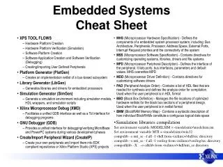
Tools • Various tools supporting such methodologies • Commercial and academic • POLIS (Berkeley), Cierto VCC (Cadence) • SpecCharts (Irvine) • STATEMATE, Rhapsody (ilogix) • Rose RT (Rational) • SCADE, Esterel Studio (Esterel Technologies) • Stateflow and Simulink (Mathworks)
Modeling Languages • Models need to be formal • Languages for describing models • Various languages exist • High level programming languages (C, C++) • Finite State Machines, Statecharts, SpecCharts, Esterel, Stateflow • Data Flow Diagrams, Lustre, Signal, Simulink • Hardware description languages (VHDL, Verilog) • Unified Modeling Language(UML)
Modeling Languages • Choice of languages depend upon the nature of computations modeled • Seq. programming models for standard data processing computations • Data flow diagrams for iterative data transformation • State Machines for controllers • HDLs for hardware components
Reactive Systems • Standard Software is a transformational system • Embedded software is reactive I O T. S.
R. S. Reactive Systems
RS features • Non-termination • Ongoing continuous relationship with environment • Concurrency (at least system and environment) • Event driven • Events at unpredictable times • Environment is the master • Timely response (hard and soft real time) • Safety - Critical • Conventional models inadequate
Finite State Machines • One of the well-known models • Intuitive and easy to understand • Pictorial appeal • Can be made rigorous • Standard models for Protocols, Controllers, HW
A Simple Example • 3 bit counter • C – count signal for increments • Resets to 0 when counter reaches maximum value • Counter can be described by a program with a counter variable (Software Model) • Or in detail using flip flops, gates and wires (Hardware model)
State Machine Model • Counter behaviour naturally described by a state machine • States determine the current value of the counter • Transitions model state changes to the event C. • Initial state determines the initial value of the counter • No final state (why?)
Precise Definition < Q, q0, S, T> • Q – A finite no. of state names • q0 – Initial state • S – Edge alphabet Abstract labels to concrete event, condition and action • T – edge function or relation
Semantics • Given the syntax, a precise semantics can be defined • Set of all possible sequences of states and edges • Each sequence starts with the initial state • Every state-edge-state triples are adjacent states connected by an edge • Given a FSM, a unique set of sequences can be associated • Language accepted by a FSM
Abstract Models • Finite State machine model is abstract • Abstracts out various details • How to read inputs? • How often to look for inputs? • How to represent states and transitions? • Focus on specific aspects • Easy for analysis, debugging • Redesign cost is reduced • Different possible implementations • Hardware or Software • Useful for codesign of systems
Intuitive Models • FSM models are intuitive • Visual • A picture is worth a thousand words • Fewer primitives – easy to learn, less scope for mistakes and confusion • Neutral and hence universal applicability • For Software, hardware and control engineers
Rigorous Models • FSM models are precise and unambiguous • Have rigorous semantics • Can be executed (or simulated) • Execution mechanism is simple: An iterative scheme state = initial_state loop case state: state 1: Action 1 state 2: Action 2 . . . end case end
Code Generation • FSM models can be refined to different implementation • Both HW and SW implementation • Exploring alternate implementations • For performance and other considerations • Automatic code generation • Preferable over hand generated code • Quality is high and uniform
States and Transitions • Many Flavors of State Machines • edge labeled - Mealy machines • state labeled - Kripke structures • state and edge labeled - Moore machines • Labels • Boolean combination of input signals and outputs • communication events (CSP, Promela)
Another Example A Traffic Light Controller • Traffic light at the intersection of High Way and Farm Road • Farm Road Sensors (signal C) • G, R – setting signals green and red • S,L - Short and long timer signal • TGR - reset timer, set highway green and farm road red
Another Example A Simple Lift Controller 3-floor lift • Lift can be in any floor • Si - in floor I • Request can come from any floor • ri - request from floor I • Lift can be asked to move up or down • uj,dj - up/down to jth floor
Nondeterminism • Suppose lift is in floor 2 (State S 2 ) • What is the next state when when requests r1 and r3 arrive? • Go to S1 • Or go to S3 • The model non committal – allows both • More than one next state for a state and an input • This is called nondeterminism • Nondeterminism arises out of abstraction • Algorithm to decide the floor is not modeled • Models can be nondeterministic but not real lifts!
Nondeterminism • Models focus attention on a particular aspect • The lift model focussed on safety aspects • And so ignored the decision algorithm • Modeling languages should be expressive • Std. Programming languages are not • Use another model for capturing decision algorithm • Multiple models, separation of concerns • Independent analysis and debugging • Management of complexity • Of course, there should be a way of combining different models
C-model enum floors {f1, f2, f3};enum State {first, second, third};enum bool {ff, tt};enum floors req, dest; enum bool up, down = ff;enum State cur_floor = first;req = read_req(); while (1){ switch (cur_floor) { case first: if (req == f2) {up = tt; dest = f2;}else if (req == f3) {up = tt; dest = f3;}else { up == ff; down = ff;}; break;
C- model case second: if (req == f3) {up = tt; dest = f3;} else if (req == f1) { up = ff; down = tt; dest = f1;}else { up == ff; down = ff;}; break; case third: if (req == f2) {up = ff; down = tt; dest = f2;}else if (req == f1) { up = ff; down = tt; dest = f1;} else { up == ff; down = ff;}; break; }; /* end of switch */ req = read_req(); } /* end of while */
Suitability of C • C not natural for such applications • Various problems • Events and states all modeled as variables • Not natural for even oriented embedded applications • States are implicit (control points decide the states) • No abstract description possible • Commitment to details at an early stage • Too much of work when the design is likely to be discarded
Exercise • Is the C model non-deterministic? • What happens when two requests to go in different directions arrive at a state?
T > tmax on off T’ = K1 T’ = K2 T < tmin Yet Another example • A Simple Thermostat controller
Summary • Finite number of states • Initial state • No final state (reactive system) • Non determinism (result of abstraction) • Edges labeled with events • Behavior defined by sequences of transitions • Rigorous semantics • Easy to simulate and debug • Automatic Code generation