Download
1 / 51
530 likes | 1.08k Views
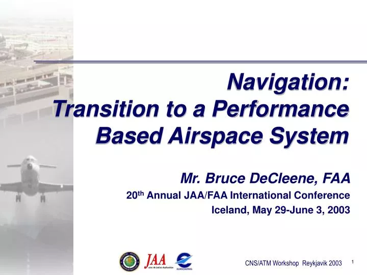
Navigation: Transition to a Performance Based Airspace System. Mr. Bruce DeCleene, FAA 20 th Annual JAA/FAA International Conference Iceland, May 29-June 3, 2003. Overview. RNP Roadmap US Europe Infrastructure Considerations - The Role of GNSS Conclusion. Containment radius.

E N D
Navigation:Transition to a Performance Based Airspace System Mr. Bruce DeCleene, FAA 20th Annual JAA/FAA International Conference Iceland, May 29-June 3, 2003
Overview • RNP Roadmap • US • Europe • Infrastructure Considerations - The Role of GNSS • Conclusion
Containment radius 95 % Accuracy established as 1 X RNP Containment Region (2 X RNP) composed of containment integrity and containment continuity Required Navigation Performance • RNP: A statement of navigation performance for operation in a defined airspace (ICAO Annex 6) • RNP airspace: Airspace, route(s), and leg(s) where minimum navigation performance requirements (RNP) have been established, and aircraft must meet or exceed that performance to fly in that airspace (RTCA SC181/EUROCAE WG.13)
RNP Roadmap Implementation Principles • Collaboration • Incremental procedure implementation • measure benefits • resolve issues • apply lessons learned • Incentive-based approach in near term, • possible mandate considerations in mid- and long-term • Strategy based on harmonization considerations
RNP Roadmap Structure • Domains • Timeframes (Near, Mid, Far term) • Structured around operational goals • Approach • Terminal • En Route Integration to occur across domains via projects like NAR RNP Airspace, Routes, Offsets Vector-Free Arrivals Optimized Departures RNP Approaches Far term Near term Mid term
Limited Implementation Public TERPS, flight inspection, AVN training, Draft AC 90-RNP, special authorization (Part 97) • Turnkey: Published/signed criteria, published AC 90-RNP • Builds upon near-term implementation and lessons learned. • Public procedures in all domains Implementation Strategy • “Specials”: Use Core TERPs and Core guidance materials (i.e. AC 90-RNP, FAA bulletins, etc.) with goal of moving towards “limited implementation” ASAP • Enables near term implementations, “specials” - via Lead Operator • Enables data collection, lessons learned, issue resolution • Addresses near term operational impacts
RNP Airspace, Routes, Offsets (incremental RNP 2 then RNP 1) Mid term: Enabling flight paths separated by 4 nmi or less Vector-Free 3D Arrivals (integrated with Approaches) RNAV vs RNP Mid-term: Enabling flight paths separated by 3 nmi or less Multiple Departure Gates (3D DPs starting at DER) via RNAV L1/L2 vs. RNP 1/2 Mid term: Enabling flight paths separated by 3 nmi or less RNP and RNAV Strategy Issue
European Navigation Strategy 2000 2005 2010 2015 TMA Operations RNP 1 RNAV mandatory in all TMAs En-route BRNAV at all levels RNAV routes RNP 1 accuracy RNP 1 RNAV mandatory en-route AWO and A-SMGCS 4D RNAV Conventional SIDs/STARs P RNAV mandatory in selected TMAs RNAV SIDs/STARs Provide NPA Provide Cat I/II/III PA Provide runway guidance Rationalisation of the Ground Infrastructure for all phases of flight Terminal Airspace limitations seen as the main driver
Operating RNAV in Terminal Airspace • Basic RNAV not good enough! • In Europe about 6 different aircraft TMA RNAV requirements • Issues: accuracy, functionality, data integrity. • Variety of charting principles, ATC procedures, etc. • No approval associated with use of RNAV equipment for TMA RNAV
SOLUTION • ECAC States have agreed to introduce a common Terminal; Airspace approach: • P-RNAV required where Basic RNAV is not sufficient • Common P-RNAV procedure design principles, based on common material • Phase out variations in RNAV requirements • Given current situation, get this in place ASAP (but allowing for all enablers to be available)
Main P-RNAV enablers • JAA TGL/10 with clarification material => available • TGL/10 Data Integrity => practical solution agreed with JAA (certification data providers) • Approved ICAO Doc 7030 amendment (Phraseology, ATC & flight deck procedures, etc) => comments close 2 May 2003 • PANS-OPS procedure design guidance => available • Operator, Authority and Industry awareness => on steam (but requires State planning as input)
RNP -RNAV Business case undertaken in 2002 • Identified as a way forward subject to demonstration of capacity gains • Simulations undertaken in 2002 • Full analysis complete by end 2003 Issue: • P-RNAV NOT mandatory (conventional procedure remain until 2010) • However if re-equipping for P-RNAV consider longer term requirements
Approach Initiatives • Vertically-guided approaches! • Implementing approaches based on RNAV and barometric VNAV • Safety benefit, limited improvement in minima over non-precision approach • XX approaches published • Implementing new approaches (APV-I) based on GNSS vertical guidance • Safety benefit, significant improvement in minima over non-precision approach • First approaches to be published 9/03 • Added to future RNAV approaches • Ultimately over 4000 runway ends
LNAV/VNAV (556 m by 50 m) GLS (40 m by 12 m) LPV (40 m by 50 m) LNAV/VNAV – GLS – LPVPerformance Comparison
Infrastructure Considerations • Performance • Guidance Materials • Benefits • Equipage • Terminology
RNAV (Performance) based on • GNSS • DME/DME • IRS • VOR(DME)* May have some limited requirement in some [remote] airspace areas Limited RNAV or conventional nav
2000 2005 2010 2015 NDB VOR DME GPS SBAS GBAS NDB VOR DME GPS ILS Cat I ILS Cat II/III MLS Cat III SBAS Cat I GBAS Cat I/II/III European Infrastructure En-Route Approach / Landing / Departure / A-SMGCS Cat I
GNSS • GPS • ABAS (RAIM, AIME) • SBAS (EGNOS, WAAS, etc.) • GBAS • Galileo • GPS Modernization
EUROPEAN COMMISSION The European Approach EGNOS EGNOS (European Geostationary Navigation Overlay Service) is an initiative of the European Commission, Eurocontrol and ESA GALILEO: Achieve European sovereignty and service guarantees through dedicated system under civil control: Galileo, operational by 2008 European Policy European Commission
FIX FOM 1 N 42* 01” 46.12” W 091* 38’ 54.36” EL + 00862 ft 3 menu 1 ON 2 4 5 6 7 WPT 8 POS 9 NAV CLR MARK 0 OFF NUM LOCK ZEROIZE Rockwell GPS III Mission and System Description The GPS III Maintain Space User Service Second Civil Signal Third Civil Signal • Relook at entire GPS Architecture to • Achieve long term GPS performance goals • Improve long term efficiencies • Ensure GPS properly assesses and is synergized with • Military and Civil Needs/Systems • Possible augmentation opportunities • Ensure best GPS for the next 30 years
Conclusion • Collaboration is paramount to success • Incremental procedure implementation • Incentive-based approach in near term • Transition strategy must include harmonization considerations • GNSS remains a fundamental component
Backup Slides Navigation - DeCleene
Vertical Capability WPT Vertical angle (-3.00º) Vertical flight path Speed and altitude constraint at waypoint (170/2460) • - Waypoint altitude constraint • - Vertical angle • - Waypoint speed constraint (optional)
RNP Roadmap Implementation Principles (concluded) • Incentive-based approach in near term, • possible mandate considerations in mid- and long-term • Airspace redesign based on new RNP criteria for maximum benefit • Integration with other programs to maximize synergy • Strategy based on harmonization considerations
Goals: Goals: Goals: Improve airport access (lower minima) and IFR capacity at locations constrained by airspace separation criteria, closely spaced parallels, or converging runways Vertically guided approaches to all runway ends Improve airport access at locations constrained by airspace/environmental considerations Tool set: Tool set: Remove DME/DME NA from existing RNAV (GPS) procedures Tool set: RF inside the FAF for environmental considerations Publish 8260.51 Public RNP-0.3 instrument approach procedures Enable VNAV at all applicable runway ends RNP<.3 criteria for environmental considerations Publish 8260.48 linear TERPS RNP<.3 (2xRNP, no transition) criteria Guided missed approach with RNP<1 for environmental reduced vertical criteria for lower minima at sites with obstacles Guided missed with RNP<1 for sites with converging runways RF criteria for use outside and possibly inside the FAF Reduced vertical criteria to exploit vertical separation RPAT Concept De-conflict adjacent airport arrival flows Goal Structure: RNP Approaches Capacity Environment Safety / Training
Goals: Goals: Goals: Reduce path width permitting more Routes in a lateral space Improve arrival and departure traffic management using multiple arrival and departure flows between en route and terminal Reduce length of paths with fewer legs and more direct routes Use parallel tactical offsets for passing Flights around slower flights, and for Maneuvering due to traffic Tool set: Tool set: Tool set: Develop criteria for airway en route RNP-2 (8 nmi track-to-track, no radar required) Develop criteria for RNP 1 (2xRNP and 1xRNP) Develop criteria for RNP 2 (8nmi Track-to-track; radar not required) Develop concepts, procedures, and automation requirements for strategic ATM between ER/terminal Determine aircraft capability requirements Develop criteria for airway en route RNP 1 (4 nmi track-to-track; radar not required) Conduct airspace redesign Conduct airspace redesign Develop 3D RNP criteria for en route Develop procedures for offsets Low Altitude Airspace Access Develop controller automation Requirements and upgrades Goal: Develop criteria for RNP routes at low altitudes Increased low altitude off-airway flight and access to lower altitudes for published routes (through lower MEA). Tool set: Develop criteria for performance based separation (radar not required), Redesign airspace, Determine aircraft capability requirements Goal Structure: RNP En Route Environmental/ Economic Strategic ATM Capacity/Efficiency
Goals: Goals: Goals: Improve arrival and departure traffic management using multiple arrival and departure flows between en route and terminal Improve terminal ingress and egress, reduce Taxi-out times, and reduce/eliminate static restrictions by increasing throughput that is limited due to ground based navigational constraints, and throughput that is limited due to closely spaced procedures, airspace, adjacent airport flows, or airport configurations. Improve operations to minimize impacts on noise sensitive areas Tool set: Develop fuel efficient 3D procedures to minimize fuel burn and engine emissions Develop criteria for RNP 1 (2xRNP and 1xRNP) Tool set: Tool set: Playbook routes 3D SIDs and STAR procedures RNP overlay and non-overlay procedures Conduct airspace redesign Multiple arrival/departure gates 3D procedures starting from DER Multiple runway transitions ARTCC/TRACON/Command Center interaction RNP 1 procedures Subsets of procedures RNP < 1 - arrival to departure Develop 3D SIDs and STARs RF Legs and diverse vector areas - arrival to arrival - airport to airport SUA or restricted airspace locations Playbook/escape routes Develop criteria for RNP 1 (2xRNP and 1xRNP) Airspace redesign based on RNP 1 ARTCC and Command Center interaction RF Legs and diverse vector areas Goal Structure: RNP Terminal Environmental/ Economic Strategic ATM Capacity/Efficiency
Operating RNAV in Terminal Airspace (1) • Increased use of RNAV in ECAC Terminal Airspace: • Connectivity to en-route Basic RNAV network • Advantages RNAV (flexibility, accuracy, workload, ..) • Increased Aircraft Capabilities • However. . .inconsistent application
TARGET SITUATION <MSA MSA> ] Option P + P Option C P + AVOID ] RNAV Mix Option + B C C + Option C VARIETY RNAV Not an Option! VARIETY RNAV P = P-RNAV B = B-RNAV C = Conventional Variety RNAV = National RNAV requirements not associated with an ECAC-wide accepted approval requirement
TIME SCALES Terminal Airspace Target Situation where RNAV is currently in operation or introduction is already published: • Major TMAs: by Nov 2004 • Other TMAs: by April 2005 New RNAV publications: • To directly apply Target Situation
EUROPEAN COMMISSION GALILEO & GPS • Vertical Accuracy improved from 7.5 m to 4.5 meters worldwide. • Visibility under high masking angle conditions highly improved.
The APV implementation program in France • European level: preparation of EGNOS operations: • Creation of an entity to operate EGNOS, • With other partners civil aviations (EOIG - ESSP) • Preparation of EGNOS certification, • With EOIG and Eurocontrol • National level: preparation of EGNOS operations: • In-flight trials of EGNOS APV • Creation of an Ad Hoc group in 2002 to study EGNOS APV procedures deployment • With participation of Eurocontrol and ASECNA
The APV implementation program in France • EGNOS APV procedures deployment • First step: design procedures for target runways to quantify benefits over NPA approaches (end-2003) • Next steps to achieve initial APV operational capability will be : 1. experimental phase with in-flight tests 2. involvement of users (airports and regions) : • Operational issues, • APV operational safety case (certification), 3. pre-operational phase with selected runways and involving operators (mid-2005).
US SBAS APV operational implementation plan • WAAS to be commissioned in July, 2003 • Provide capability to conduct VNAV approaches • First APV-I procedure to be commissioned in September, 2003 • Developed operational concept for APV operations • Title will be « LPV » approach • Obstacle clearance criteria adapted from ILS • Ultimately, APV-I procedures will be commissioned for over 4000 runway ends
APV Conclusions • GNSS APV is now a reality with SBAS • Improve safety with operational benefits • In France, EGNOS APV will complement existing ILS Cat I infrastructure • An operational group to prepare APV deployment starting mid-2005 is in place • In the US, APV commissioning using WAAS is starting in 2003 • APV-I commissioning on all USA runway ends will follow
Benefits • From Pilot Viewpoint, System Behaves Like ILS • Can Achieve Minima Below 325’ (1 mi.) • Makes Vertical Guidance Safety Benefit Accessible to General Aviation • Compared to LNAV/VNAV: • No Cold Weather Altimeter Correction Limitation • Allows operation with Remote Altimeter Setting (with appropriate minima penalty) • Higher System Integrity: “Precision-like” • Allows Use of Modified ILS TERPS Criteria
Terminology/Classification • Proposal Restricts Minima to 250’ HAT (3/4 mi. Visibility without Lights) • Visibility Limited Based on Supporting Infrastructure • AC 150/5300-13, Appendix 16, Table A16-1B • “Precision Approach” Infrastructure Not Required • Current ICAO Annex 6 Approach Classification: • Instrument Approach Procedure with Vertical Guidance • Proposed ICAO Annex 10 Performance Definition: • APV-I
15000 10000 5000 Distance from C/L (ft) 0 20000 25000 35000 10000 15000 30000 -5000 5000 -5000 -10000 Distance from Runway Threshold (ft) -15000 A Comparison of Lateral Obstacle Clearance Criteria(LNAV/VNAV vs. LPV) LNAV/VNAV OCS LPV OCS
“W” OCS has 34:1 slope for a 3 degree GS LPVObstacle Clearance Surfaces
668' HAT 3 Glideslope o 250' HAT 185' HAT 23:1 Baro-VNAV OCS 34:1 Precision OCS Best Case 27:1 LPV OCS 48' Touchdown Elevation 954' 200' 2,379' 1,237' 7,983' 954' 1,154' 3,533' 4,770' 12,753' LPV Vertical Criteria WAAS NSE Does Not Degrade with Distance from Threshold, & At 668’ HAT, WAAS & ILS NSE Equivalent. Above 668’ HAT, LPV Uses ILS OCS; Validates Use of ILS Criteria Adjusted for 50 M Vertical Alert Limit
Controlling ObstaclesLPV&LNAV/VNAV OCS 15000 10000 5000 Distance from C/L (ft) 0 -5000 0 5000 10000 15000 20000 25000 30000 35000 -5000 -10000 Distance from RWT (ft) -15000
3500 3000 2500 2000 Number of Runway Ends 1500 1000 500 0 250- 259- 328- 396- 466- 535- 604- More GQS 258 327 395 465 534 603 740 Fail Height Above Touchdown (HAT) in feet LPV EstimatedApproach Minima 5073 Runway Ends at 1534 Airports Average: 272 ft Median: 250 ft % < 258ft: 81%
EUROPEAN COMMISSION Inclination 56 degrees The Satellite Constellation GALILEO • 30 satellites in three Medium Earth Orbit MEO planes at 23616 km altitude • 1 satellite per orbital plane is a spare • Inclination of orbital planes 56 degrees • One revolution 14 hours 4 min • Ground track repeat 10 days
EUROPEAN COMMISSION GALILEO The Master Schedule DEPLOYMENT OPERATIONS DEFINITION DEV & VALIDATION 2000 2001 2002 2003 2004 2005 2006 2007 2008 … Definition Development & Validation PHASE B2 PSDR CDR SQR PHASE CD In-Orbit Validation (IOV) IOVR Test Bed (GSTB) Full Deployment Operations Local Elements User Receiver / Applications Technology Developments PDR: Preliminary Design Review SQR: System Qualification Review Launches CDR: Critical Design Review IOVR: In-Orbit Validation Review
Pre-Modernization Current Signals L1 C/A L1, L2 P(Y) GPS Block IIR Modernization Post-Modernization • Modernized Signals • L1 C/A • L1, L2 P(Y) • L2 C/A or L2C • L1, L2 M-Code First Launch Planned for 2004