Download
1 / 67
670 likes | 812 Views
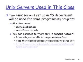
Unix Servers Used in This Class. Two Unix servers set up in CS department will be used for some programming projects Machine name: eustis.eecs.ucf.edu eustis2.eecs.ucf.edu You can connect to them only in campus network If outside, set up VPN to campus network first

E N D
Unix Servers Used in This Class • Two Unix servers set up in CS department will be used for some programming projects • Machine name: • eustis.eecs.ucf.edu • eustis2.eecs.ucf.edu • You can connect to them only in campus network • If outside, set up VPN to campus network first • Read the following webpage to learn how to setup VPN • http://www.cst.ucf.edu/about/telecommunications/network-services/vpn/ Introduction
Need to use SSH to remote login • SSH free software (many many others): • Command shell client: PuTTY http://www.putty.org/ • File transfer: WinSCP (for windows) http://winscp.net/eng/index.php • Student can log in using default password Pyymmdd (birth year, month and day). • For any login problems, please email help@eecs.ucf.edu Introduction
Basic Usage of Unix • You only need to remember a few basic commands for using the Eustis machine for this class • Editor: pico (or edit on your computer and upload the code to eustis) • Command: • cd, mkdir, rmdir, chdir, • cp, rm, ls, man, • There are many tutorials online • http://www.ee.surrey.ac.uk/Teaching/Unix/ • http://freeengineer.org/learnUNIXin10minutes.html • Command line reference: http://www.pixelbeat.org/cmdline.html Introduction
Basic Usage of Linux • You can use PuTTY to open many independent shells • For the program project 1, you can run client code on one eustis machine, and the server code in another eustis machine. Introduction
Chapter 1: roadmap 1.1 What is the Internet? 1.2 Network edge • end systems, access networks, links 1.3 Network core • circuit switching, packet switching, network structure 1.4 Delay, loss and throughput in packet-switched networks 1.5 Protocol layers, service models 1.6 Networks under attack: security 1.7 History Introduction
mesh of interconnected routers the fundamental question: how is data transferred through net? circuit switching: dedicated circuit per call: telephone net packet-switching: data sent thru net in discrete “chunks” The Network Core Introduction
Alternative core: circuit switching end-end resources allocated to, reserved for “call” between source & dest: In diagram, each link has four circuits. call gets 2nd circuit in top link and 1st circuit in right link. dedicated resources: no sharing circuit-like (guaranteed) performance circuit segment idle if not used by call (no sharing) Commonly used in traditional telephone networks Introduction
network resources (e.g., bandwidth) divided into “pieces” pieces allocated to calls resource piece idle if not used by owning call (no sharing) Network Core: Circuit Switching • dividing link bandwidth into “pieces” • frequency division • time division Introduction
Example: 4 users FDM frequency time TDM (GSM uses this) frequency time Circuit Switching: FDM and TDM TDMA: Time Division Multiplexing Access Introduction
Numerical example • How long does it take to send a file of 640,000 bits from host A to host B over a circuit-switched network? • All links are 1.536 Mbps • Each link uses TDM with 24 slots/sec • 500 msec to establish end-to-end circuit Let’s work it out! Introduction
each end-end data stream divided into packets user A, B packets share network resources each packet uses full link bandwidth resources used as needed Network Core: Packet Switching Bandwidth division into “pieces” Dedicated allocation Resource reservation C A D B Introduction
Network Core: Packet Switching resource contention: • aggregate resource demand can exceed amount available • congestion: packets queue, wait for link use • store and forward: packets move one hop at a time • Node receives complete packet before forwarding C A D B Introduction
Packet-switching: store-and-forward takes L/R seconds to transmit (push out) L-bit packet into link at R bps store and forward:entire packet must arrive at router before it can be transmitted on next link one-hop numerical example: L = 7.5 Mbits R = 1.5 Mbps one-hop transmission delay = 5 sec L bits per packet 1 3 2 source destination R bps R bps • end-end delay = 2L/R (assuming zero propagation delay) more on delay shortly … Introduction
Sequence of A & B packets does not have fixed pattern, shared on demand statistical multiplexing. D E Packet Switching: Statistical Multiplexing 10 Mb/s Ethernet C A statistical multiplexing 1.5 Mb/s B queue of packets waiting for output link Introduction
Two key network-core functions routing:determines source-destination route taken by packets • routing algorithms forwarding:move packets from router’s input to appropriate router output routing algorithm local forwarding table header value output link 0100 0101 0111 1001 3 2 2 1 1 0111 2 3 dest address in arriving packet’s header Network Layer
Packet switching versus circuit switching example: 1 Mb/s link each user: 100 kb/s when “active” active 10% of time circuit-switching: 10 users packet switching: with 35 users, probability > 10 active at same time is less than .0004 * packet switching allows more users to use network! Q: how did we get value 0.0004? Q: what happens if > 35 users ? N users ….. 1 Mbps link Introduction * Check out the online interactive exercises for more examples
Great for bursty data resource sharing simpler, no call setup Excessive congestion: packet delay and loss protocols needed for reliable data transfer, congestion control Q: How to provide circuit-like behavior? bandwidth guarantees needed for audio/video apps QoS – Quality of Service still an unsolved problem (chapter 7) Is packet switching a “slam dunk winner?” Packet switching versus circuit switching Introduction
Internet structure: network of networks • End systems connect to Internet via access ISPs (Internet Service Providers) • Residential, company and university ISPs • Access ISPs in turn must be interconnected. • So that any two hosts can send packets to each other • Resulting network of networks is very complex • Evolution was driven by economics and national policies • Let’s take a stepwise approach to describe current Internet structure
Internet structure: network of networks Question: given millions of access ISPs, how to connect them together? … … … … access net access net access net access net access net access net access net access net access net access net access net access net access net access net access net access net … …
Internet structure: network of networks Option: connect each access ISP to every other access ISP? … … … … connecting each access ISP to each other directly doesn’t scale: O(N2) connections. … … … … access net access net access net access net access net access net access net access net access net access net access net access net access net access net access net access net … … …
Internet structure: network of networks Option: connect each access ISP to a global transit ISP? Customer and provider ISPs have economic agreement. … … … … globalISP access net access net access net access net access net access net access net access net access net access net access net access net access net access net access net access net … …
Internet structure: network of networks But if one global ISP is viable business, there will be competitors …. … … ISP B ISP A ISP C … … access net access net access net access net access net access net access net access net access net access net access net access net access net access net access net access net … …
Internet structure: network of networks But if one global ISP is viable business, there will be competitors …. which must be interconnected Internet exchange point … … ISP B ISP C ISP A IXP IXP … … access net access net access net access net access net access net access net access net access net access net access net access net access net access net access net access net peering link … …
Internet structure: network of networks … and regional networks may arise to connect access nets to ISPs … … ISP B ISP C ISP A IXP IXP … … access net access net access net access net access net access net access net access net access net access net access net access net access net access net access net access net regional net … …
Internet structure: network of networks … and content provider networks (e.g., Google, Microsoft, Akamai ) may run their own network, to bring services, content close to end users … … ISP B ISP B ISP A IXP IXP … Content provider network … access net access net access net access net access net access net access net access net access net access net access net access net access net access net access net access net regional net … …
Internet structure: network of networks at center: small # of well-connected large networks “tier-1” commercial ISPs(e.g., Level 3, Sprint, AT&T, NTT), national & international coverage content provider network (e.g, Google): private network that connects its data centers to Internet, often bypassing tier-1, regional ISPs Tier 1 ISP Tier 1 ISP Google IXP IXP IXP Regional ISP Regional ISP access ISP access ISP access ISP access ISP access ISP access ISP access ISP access ISP Introduction
Tier-1 ISP: e.g., Sprint POP: point-of-presence to/from backbone peering … … … … … to/from customers Introduction
Chapter 1: roadmap 1.1 What is the Internet? 1.2 Network edge • end systems, access networks, links 1.3 Network core • circuit switching, packet switching, network structure 1.4 Delay, loss and throughput in packet-switched networks 1.5 Protocol layers, service models 1.6 Networks under attack: security 1.7 History Introduction
packets queue in router buffers packet arrival rate to link exceeds output link capacity packets queue, wait for turn packet being transmitted (delay) packets queueing (delay) free (available) buffers: arriving packets dropped (loss) if no free buffers How do loss and delay occur? A B Introduction
1. nodal processing: check bit errors determine output link transmission A propagation B nodal processing queueing Four sources of packet delay • 2. queueing • time waiting at output link for transmission • depends on congestion level of router Introduction
3. Transmission delay: R=link bandwidth (bps) L=packet length (bits) time to send bits into link = L/R 4. Propagation delay: d = length of physical link s = propagation speed in medium (~2-3x10⁸ m/sec) propagation delay = d/s transmission A propagation B nodal processing queueing Delay in packet-switched networks Note: s and R are very different quantities! Introduction
Nodal delay • dproc = processing delay • typically a few microsecs or less • dqueue = queuing delay • depends on congestion • dtrans = transmission delay • = L/R, significant for low-speed links • dprop = propagation delay • a few microsecs to hundreds of msecs Introduction
R: link bandwidth (bps) L: packet length (bits) a: average packet arrival rate Queueing delay (revisited) average queueing delay traffic intensity = La/R • La/R ~ 0: avg. queueing delay small • La/R 1: avg. queueing delay large • La/R > 1: more “work” arriving than can be serviced, average delay infinite! La/R ~ 0 La/R 1 * Check out the Java applet for an interactive animation on queuing and loss Introduction
“Real” Internet delays and routes • What do “real” Internet delay & loss look like? • Traceroute program: provides delay measurement from source to router along end-end Internet path towards destination. For all i: • sends three packets that will reach router i on path towards destination • router i will return packets to sender • sender times interval between transmission and reply. 3 probes 3 probes 3 probes Introduction
“Real” Internet delays and routes traceroute: gaia.cs.umass.edu to www.eurecom.fr Three delay measurements from gaia.cs.umass.edu to cs-gw.cs.umass.edu 1 cs-gw (128.119.240.254) 1 ms 1 ms 2 ms 2 border1-rt-fa5-1-0.gw.umass.edu (128.119.3.145) 1 ms 1 ms 2 ms 3 cht-vbns.gw.umass.edu (128.119.3.130) 6 ms 5 ms 5 ms 4 jn1-at1-0-0-19.wor.vbns.net (204.147.132.129) 16 ms 11 ms 13 ms 5 jn1-so7-0-0-0.wae.vbns.net (204.147.136.136) 21 ms 18 ms 18 ms 6 abilene-vbns.abilene.ucaid.edu (198.32.11.9) 22 ms 18 ms 22 ms 7 nycm-wash.abilene.ucaid.edu (198.32.8.46) 22 ms 22 ms 22 ms 8 62.40.103.253 (62.40.103.253) 104 ms 109 ms 106 ms 9 de2-1.de1.de.geant.net (62.40.96.129) 109 ms 102 ms 104 ms 10 de.fr1.fr.geant.net (62.40.96.50) 113 ms 121 ms 114 ms 11 renater-gw.fr1.fr.geant.net (62.40.103.54) 112 ms 114 ms 112 ms 12 nio-n2.cssi.renater.fr (193.51.206.13) 111 ms 114 ms 116 ms 13 nice.cssi.renater.fr (195.220.98.102) 123 ms 125 ms 124 ms 14 r3t2-nice.cssi.renater.fr (195.220.98.110) 126 ms 126 ms 124 ms 15 eurecom-valbonne.r3t2.ft.net (193.48.50.54) 135 ms 128 ms 133 ms 16 194.214.211.25 (194.214.211.25) 126 ms 128 ms 126 ms 17 * * * 18 * * * 19 fantasia.eurecom.fr (193.55.113.142) 132 ms 128 ms 136ms trans-oceanic link * means no response (probe lost, router not replying) Under Windows is “tracert” Introduction
Traceroute from My Home Computer (last year) Introduction
Traceroute from My Home Computer (another time) Introduction
Online Traceroute Tools • Because UCF campus network blocks all ICMP packets, you need an outside machine to try it. • Try on http://tools.pingdom.com/ping/ • Try from different countries from www.traceroute.org • Check traceroute virtual path at: • http://traceroute.monitis.com/ and • http://www.yougetsignal.com/tools/visual-tracert/ Introduction
Packet loss • queue (aka buffer) preceding link in buffer has finite capacity • when packet arrives to full queue, packet is dropped (aka lost) • lost packet may be retransmitted by previous node, by source end system, or not retransmitted at all (UDP) buffer (waiting area) packet being transmitted A B packet arriving to full bufferis lost Introduction
pipe that can carry fluid at rate Rsbits/sec) pipe that can carry fluid at rate Rcbits/sec) Throughput • throughput: rate (bits/time unit) at which bits transferred between sender/receiver • instantaneous: rate at given point in time • average: rate over long(er) period of time link capacity Rcbits/sec link capacity Rsbits/sec server, with file of F bits to send to client server sends bits (fluid) into pipe Introduction
Rs > RcWhat is average end-end throughput? Rsbits/sec Rcbits/sec Rcbits/sec bottleneck link link on end-end path that constrains end-end throughput Throughput (more) • Rs < RcWhat is average end-end throughput? Rsbits/sec Introduction
Throughput: Internet scenario • per-connection end-end throughput: min(Rc,Rs,R/10) • in practice: Rc or Rs is often bottleneck Rs Rs Rs R Rc Rc Rc 10 connections (fairly) share backbone bottleneck link Rbits/sec Introduction
Chapter 1: roadmap 1.1 What is the Internet? 1.2 Network edge • end systems, access networks, links 1.3 Network core • circuit switching, packet switching, network structure 1.4 Delay, loss and throughput in packet-switched networks 1.5 Protocol layers, service models 1.6 Networks under attack: security 1.7 History Introduction
Networks are complex! many “pieces”: hosts routers links of various media applications protocols hardware, software Question: Is there any hope of organizing structure of network? Or at least our discussion of networks? Protocol “Layers” Introduction
ticket (complain) baggage (claim) gates (unload) runway landing airplane routing ticket (purchase) baggage (check) gates (load) runway takeoff airplane routing airplane routing Organization of air travel • a series of steps Introduction
ticket ticket (purchase) baggage (check) gates (load) runway (takeoff) airplane routing ticket (complain) baggage (claim gates (unload) runway (land) airplane routing baggage gate airplane routing airplane routing takeoff/landing airplane routing departure airport intermediate air-traffic control centers arrival airport Layering of airline functionality Layers: each layer implements a service • via its own internal-layer actions • relying on services provided by layer below Introduction
Why layering? Dealing with complex systems: • explicit structure allows identification, relationship of complex system’s pieces • layered reference model for discussion • modularization eases maintenance, updating of system • change of implementation of layer’s service transparent to rest of system • e.g., change in gate procedure doesn’t affect rest of system • layering considered harmful? • Duplicate functions Introduction
application: supporting network applications FTP, SMTP, STTP transport: host-host data transfer TCP, UDP network: routing of datagrams from source to destination IP, routing protocols link: data transfer between neighboring network elements PPP, Ethernet physical: bits “on the wire” application transport network link physical Internet protocol stack Introduction
presentation: allow applications to interpret meaning of data, e.g., encryption, compression, machine-specific conventions session: synchronization, checkpointing, recovery of data exchange Internet stack “missing” these layers! these services, if needed, must be implemented in application needed? application presentation session transport network link physical ISO/OSI reference model Introduction