Download
1 / 117
1.24k likes | 1.84k Views
ADC および RF-CMOS 技術の最新動向. その1. 東京工業大学 大学院理工学研究科 松澤 昭. 内容. CMOS 微細化とアナログ性能 微細化とアナログ性能 ミスマッチとデジタル補償技術 A/D 変換器 パイプライン型 ADC 直並列型 ADC 逐次比較型 ADC ΔΣ 型 ADC. 研究室ホームページ http://www.ssc.pe.titech.ac.jp に関連資料が掲載されています。. CMOS 微細化とアナログ性能.

E N D
ADCおよびRF-CMOS技術の最新動向 その1 東京工業大学 大学院理工学研究科 松澤 昭 A_Matsuzawa_Titech
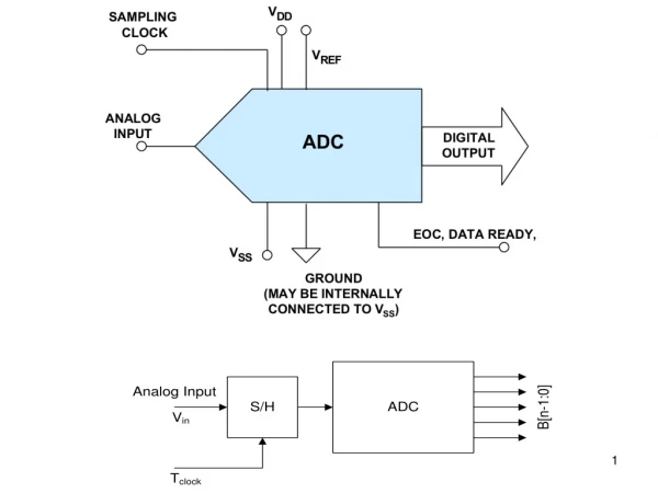
内容 • CMOS微細化とアナログ性能 • 微細化とアナログ性能 • ミスマッチとデジタル補償技術 • A/D変換器 • パイプライン型ADC • 直並列型ADC • 逐次比較型ADC • ΔΣ型ADC 研究室ホームページ http://www.ssc.pe.titech.ac.jp に関連資料が掲載されています。 A_Matsuzawa_Titech
CMOS微細化とアナログ性能 A. Matsuzawa, “ Design Challenges of Analog-to Digital Converters in Nanoscale CMOS,” IEICE, Tran. Electron., Vol. E90-C, No. 4, pp. 779-785, April 2007. A_Matsuzawa_Titech
デジタル回路におけるスケーリング則 L W tox デジタル回路においてはデバイスの各パラメータを一定比率で縮小することにより 回路の速度が向上し、低電力・低コストが達成される。 Scaling 動作電圧も1/Sにする 微細化・低電圧化により、 ・高密度化(低コスト) ・高速化 ・低消費電力 が同時に達成される A_Matsuzawa_Titech
fTと動作電圧の予測 微細化によりCMOSのfTは200GHzを超え、60GHzのミリ波応用まで可能にしている 電源電圧は1V近辺であり、大幅には下がらない vs: キャリアの飽和速度 L: チャネル長 A_Matsuzawa_Titech
アナログ回路の特性 V V dd dd 2V 2V eff eff Vsig_max v v v v out out - - out out + + V V V in in + + in in - - V V - - 4V 4V dd dd eff eff CL 2V 2V eff eff 容量負荷のOPアンプを標準的なアナログ回路として特性を記述し、 スケーリングの効果を検討する 利得: n: 増幅段数 利得帯域幅積: 第2ポール: 安定条件: SNR: 消費電力: A_Matsuzawa_Titech
アナログCMOS回路のスケーリング 1) トランスコンダクタンス: gm Veff=Vgs-VT: アナログ回路では一定にする 通常 0.2V~0.15V程度 gmは電流により決定され、不変である。 デザインルールをパラメータとするときのVdsに対するVA 2) ドレイン抵抗:rds また低電圧にすることで低下する S: スケーリングファクター 通常 1.4 A_Matsuzawa_Titech
アナログCMOS回路のスケーリング 3) 利得 利得は微細化により急速に減少する 4) 寄生容量 5)利得帯域幅積: 負荷容量が変わらなければ一定 寄生容量で決まるときは急上昇 6)第2ポール: 遮断周波数および第2ポールは微細化により急上昇する →回路はより安定する方向になる A_Matsuzawa_Titech
アナログCMOS回路のスケーリング 7)SNR: • a) 一定の信号振幅が確保できればCLは一定 • b) 微細化による電源電圧の減少により信号振幅を • 下げざるを得ない場合はCLは上昇 8) 消費電力: 低SNRの場合 a) gmおよびCLが一定とすると Cpで決まるときは 低電圧化に伴い消費電力は下がる 高SNRの場合 b) 低信号振幅により容量を上げざるを得ない場合 低電圧化に伴い消費電力は上がる A_Matsuzawa_Titech
パイプライン型ADCの分解能と容量 ADCの分解能が高くなる(高SNRになる)と必要な容量は大きくなる また、信号振幅が下がるとますます大きくなる A_Matsuzawa_Titech
Speed and power Conversion speed has saturated at 200 MHz Smaller mW/MHz is needed for low power operation. 0.3mW/MHz for 10bit and 1mW/MHz for 12bit are the bottom lines. 12b 10b 1995-2006 200MHz ISSCC 2007 A_Matsuzawa_Titech
Pipelined ADC +Vref +Vref -Vref -Vref +Vref +Vref Sample Sample 0 1 0 1 1st stage Amp. Amp. 0 1 X2 -Vref -Vref X2 Amp. Amp. 2nd Stage Sample Sample Folding I/O characteristics makes higher resolution along with pipeline stages. Hold Sample Amplify Transfer characteristics 1stStage 2nd Stage A_Matsuzawa_Titech
Technology scaling for analog Technology scaling can reduce parasitic capacitances. However signal capacitance will increase to keep the same SNR at lower voltage operation. Parasitic capacitance smaller Operating voltage lower Signal swing lower Signal capacitance larger Voltage gain lower Technology scaling Signal Cap. Signal Cap. Parasitic Cap. Parasitic Cap. Parasitic Cap. Parasitic Cap. Parasitic Cap. Parasitic Cap. A_Matsuzawa_Titech
Performance model for pipelined ADC We have developed the performance model for pipeline ADC that can treat technology scaling. A. Matsuzawa, “Analog IC Technologies for Future Wireless Systems,” IEICE, Tan on Electronics, Vol. E89-C, No.4, pp. 446-454, April, 2006. OpAmp A_Matsuzawa_Titech
Scaling and analog device and circuit parameters DR Cgs W Cgd Cap. [fF/mA],fT[GHz] W[μm/mA] DR fT L[μm] Gate width and capacitances decrease with technology scaling. (a)WN,WP[μm/mA],VA_N, VA_P[V] Veff=0.175V (b)Cpi_N, Cpi_P,Cpo[fF/mA],ωp2_N,ωp2_P[GHz] S: Scaling factor A_Matsuzawa_Titech
Determination of signal capacitance 14bit 12bit Co[pF] 10bit 8bit 0.05 0.1 0.5 Larger resolution requires larger signal capacitance. Furthermore, Voltage lowering increases signal capacitance more. Vdd 2Veff Output signal range Gain Boost amp. vout- vout+ Vin+ Vin- Vdd-4Veff 2Veff DR[μm] A_Matsuzawa_Titech
Performance curve ② ③ ① Performance exhibits convex curve. There is the peak conversion frequency and the optimum current. Current increase results in increase of parasitic capacitances and decrease of conversion frequency in the higher current region. ①Co≫Cpo,Cpi ②Cpi<Co<Cpo ③Co<Cpo、Co<Cpi A_Matsuzawa_Titech
Performance summary Scaled CMOS is effective for just low resolution ADC. Scaled CMOS is not effective for high resolution ADC. 8bit 10bit 12bit 12bit 14bit A_Matsuzawa_Titech
動作エネルギー 1MHzあたりの消費電力を推定すると、寄生容量の効果が現れるまでは消費電力と変換周波数は比例し、電流が増加すると、電流増大によるサイズ増大で寄生容量効果が現れ、動作エネルギーは増大する。 A_Matsuzawa_Titech
Optimization of Veff fc [MHz] fc [MHz] Ids [mA] Veff [V] Ids [mA] Veff [V] Optimum Veff is a function of resolution, current, and design rule. The lower Veff is recommended for scaled CMOS technology. 10 bit 12 bit, 0.18um CMOS Red: 90nm Blue: 0.18um A_Matsuzawa_Titech
Optimization of OpAmp in Pipelined ADC 90nm CMOS, near sub-threshold operation, and SC level-shift have realized 10bit 80MHz ADC with 0.8V operation and small power of 6.5mW M. Yoshioka, M. Kudo, T. Mori, and S. Tsukamoto “A 0.8V 10b 80MS/s 6.5mW Pipelined ADC with Regulated Overdrive Voltage Biasing,” ISSCC, Dig. Tech. paper, pp. 452-453, 2007. A_Matsuzawa_Titech
Results FoM=0.2pJ/step 0.08mW/MHz A_Matsuzawa_Titech
誤差補正技術 A_Matsuzawa_Titech
MOSのVTばらつきと1/fノイズ MOSのVTばらつき係数は飽和する 1/fノイズ係数は穏やかに減少 A_Matsuzawa_Titech
ウエファー内でのVT 変動 小さなトランジスタのVTばらつきはランダムであるが、 大きなデバイスでは面内傾斜が見えてくる Vt =575±18mV Vt =686±7mV A_Matsuzawa_Titech
VTミスマッチ 100 10 1 0.1 100 1000 1 10 VTミスマッチを小さくするには大きなゲート面積が必要、しかし性能劣化を招く 0.13um: Morifuji, et al., IEDM 2000 0.4um : My data 0.4um Nch 0.13um Nch Boron, w. Halo 0.13um Nch In w/o Halo* A_Matsuzawa_Titech
Influence of VT mismatch in current staring DAC Van den Bosch,.. Kluwer 2004 10 10% INL yield 50% 90% 99.7% Current mismatch (%) 1 0.1 8 6 10 14 12 Resolution (bit) Higher resolution DAC requires smaller current mismatch which is mainly caused by VT mismatch. N: resolution C: Constant determined by INL yield A_Matsuzawa_Titech
高精度アナログ回路の課題 高精度アナログ回路ではデバイスの面積が大きくなる。したがってコスト増の他、 容量の増大により周波数特性劣化と消費電力増大を招く。 Large Power dissipation Large capacitance Expensive cost High precision circuits Small mismatch Large Gate size Large area Low cutoff frequency Large capacitance A_Matsuzawa_Titech
デジタル補正を用いた DAC CAL-ADC measures non-linearity of DAC and compensates it’s non-linearity by CAL-DAC with logic 14bit 100MHz DAC External ADC Compensation circuits Y. Cong and R. L. Geiger, Iowa state university, ISSCC 2003 A_Matsuzawa_Titech
デジタル補正の効果 デジタル補正により、小さなデバイスを用いても高精度化が可能となった 従来と比べ、面積は1/50, 消費電力は1/20になった。 しかしこの方法は外部に高精度ADCが必要なため、非現実的である。 INL DNL 14bit DAC 14b 100MS/s DAC Before 1.5V, 17mW, 0.1mm2, 0.13um +/- 9 LSB +/- 5 LSB SFDR=82dB at 0.9MHz, 62dB at 42.5MHz Area: 1/50 Pd: 1/20 After +/- 0.4 LSB +/- 0.35 LSB A_Matsuzawa_Titech
A 14-bit 100-MS/s Digitally Calibrated Binary-Weighted Current-Steering CMOS DAC without Calibration ADC Yusuke Ikeda, Matthias Frey, and Akira Matsuzawa Tokyo Institute of Technology, Japan A_Matsuzawa_Titech
Motivation • To realize a high speed and a high resolution DAC, It is necessary to utilize the calibration technique. • Keep the total area small. A_Matsuzawa_Titech
デジタル補正を用いた DAC 当研究室が提案したDACは比較器で補正するもので、ADCが不要である。 Before After 14b DAC Comparator +/- 6 LSB +/- 0.5 LSB INL +/- 0.25 LSB +/- 6 LSB DNL Y. Ikeda, A. Matsuzawa, "Digital Calibration Method for Binary-Weighted Current-Steering D/A-Converters without Calibration ADC", IEICE TRANS. ELECTRON, vol. E90-C, No.6, pp.1172-1180, June. 2007 A_Matsuzawa_Titech
Error compensation by comparator Example Nature of binary weighted values 1) Measure LSB value by CAL DAC with certain accuracy. 2) Measure the error of each current source by comparator with binary search . 3) Compensate the errors by digitally Comparator RL Logic Vout Cal DAC Data in Main DAC A_Matsuzawa_Titech
MSB calibration • Comparing IMSB0 with ICMSB0 calibrated by SUBDAC • Current mirror mismatch and comparator offset are canceled by change the switch position. A_Matsuzawa_Titech
The conversion operation A_Matsuzawa_Titech
Layout (0.18um CMOS) Logic & Memory Current Sources & Current mirrors Latch & Switch 800um Comparaor Output circuits 900um A_Matsuzawa_Titech
The Simulation Results A_Matsuzawa_Titech
The Measurement Results @100MSps 6kHz Signal Before Calibration SFDR 69dBc SFDR 14dBUP After Calibration SFDR 83dBc A_Matsuzawa_Titech
The Performance Summary A_Matsuzawa_Titech
The Comparison of other DACs (mm2) A_Matsuzawa_Titech
Comparator and offset suppression Store the offset voltage in capacitor and subtract it from the signal Offset suppression Voff at sigma reaches 30mV in CMOS comparator Low gain type (feed forward method) High gain type (feedback method) Va Vo Basic CMOS comparator A_Matsuzawa_Titech
Digital Comparator offset compensation Offset voltage of latched comparator can’t be compensated by previous method. Because it has no bias point. In this case, digital method should be applied. Input terminals are shorted and the output signal controls applied voltage to the differential pair in CAL circuits so that the frequency of occurrence in differential output signals become equal. Comp_out Logic Latched CMP Vmax Vmin CCAL Cs Vmax Vmin CCAL Cs Vcom Vin+ Vin- Vcom CAL circuits “A 90nm CMOS 1.2V 6b 1GS/s Two-Step Subranging ADC” Pedro M. Figueiredo, et al., ISSCC 2006 CCAL=10 Cs A_Matsuzawa_Titech
Capacitor mismatch in pipelined ADC 1 10 bit 10 bit 0.1 Mismatch (%) 12 bit 12 bit 0.01 14 bit 14 bit 0.001 0.1 1 10 100 Capacitance (pF) Capacitor mismatch in pipelined ADC determines the conversion accuracy. For the higher resolution, the larger capacitance is needed. A_Matsuzawa_Titech
Capacitor mismatch compensation Scal Capacitor mismatch causes the large conversion value differences at the input voltage where the comparator changes the DAC voltage. Compensation method: 1) Select input signal to +/- Vref/4 2) Convert this value with VDAC=0 and +/- Vref and obtainand . 3) Add or subtract this to or from the output values S. Y. Chung and T. L. Sculley,” A Digitally Self-Calibrating 14-bit 10MHz CMOS Pipelined A/D Converter.” IEEE, JSC, Vol. 37, No.6, pp. 674-683, June 2002. A_Matsuzawa_Titech
1/fノイズ Gate Oxide Gate Oxide Trap Trap Si Si 1/f noise degrades SNR of base-band signal seriously. The 1/f noise from MOS is one or two order of magnitude higher than bipolar. The larger gate area is needed to reduction this noise. Drain current time A_Matsuzawa_Titech
Chopper amplifier Chopper technique is often to be used to reduce the effect of 1/f noise. Signal Chopped noise Signal Signal is reconstructed Signal + Noise Noise is filtered out C. C. Enz, E. A. Vittoz, and F. Krummenacher, IEEE Journal of Solid-State Circuits, Vol. 22, No. 3, pp. 335-342, June 1987 Signal Chopper freq.=1KHz 1/f noise W/O chopper W/ chopper Signal Chopper freq. LPF 1/f noise A_Matsuzawa_Titech
CT filter tuning RC or gmC circuits can realize active filter circuits, However, frequency characteristics and Q of the filter are strongly affected by Absolute value of R, C, gm and PVT fluctuation. Then, the filter tuning circuit is vital. Filter circuit can be used as oscillator, if the Q become infinity. Filter Ref clock PLL Dummy Oscillator Peak Detector frequency tuning Q tuning gm cont. go cont. gm gm go go A_Matsuzawa_Titech
Digital calibration in mixed signal SoC To keep high production yield and stable operation against PVT fluctuation, mixed signal SoC has many digital self calibration circuits. MCU controls many analog parameters. PRML circuit for DVD recorder [Analog Filter output] [RF input] Extracted Data Level Detector LMS Offset Adjust 5th order Gm-C Filter FIR Filter Viterbi Detector 7bit ADC VGA [FIR output] digital control Pick up Outputs Frequency & Phase Comparator Loop Filters Offset Control DAC Digital Calibration Analog Buffers Gain Control DACs DAC … VCO Defect Detect Wobble Filter Wobble Detect 1/N Servo Pre-Processor Extracted Clock Clock Control System Clocks ... Servo Error Signals Defect A_Matsuzawa_Titech
Issues of analog compensation techniques • Basically use discrete-time technology • Difficult to apply Continuous-Time circuits. • Needed clock causes another noise. • Some need calibration period • At power on • Needs not short time to wait the system becomes stable. • Some different situation at the power on. • Idling time on the job • Can get sufficient time for calibration? • Too much system depended. • Calibration on the job • Conventionally needs extra circuits.Cost and power consumption increase. • Needs many calibration time, if statistical methods are used. A_Matsuzawa_Titech