Download
1 / 147
1.49k likes | 1.79k Views
MSP430. microcontroller basics a description based on TI‘s MSP430 author and speaker Prof. Dr. Matthias Sturm based on TI‘s design seminar MSP430. topics. architectural overview memory configuration instruction set and addressing modes software development stack and subroutines

E N D
MSP430 microcontroller basics a description based on TI‘s MSP430 author and speaker Prof. Dr. Matthias Sturm based on TI‘s design seminar MSP430
topics • architectural overview • memory configuration • instruction set and addressing modes • softwaredevelopment • stack and subroutines • interrupt process • system clock generator • periphery • parallel ports • basic timer 1 • LCD driver module • ADC • 8-bit interval timer / counter • timer / port module • watchdog timer module
typically microcontroller applications for the MSP430 family • Handheld Measurement • Air Flow measurement • Alcohol meter • Barometer • Data loggers • Emission/Gas analyser • Temperature measurement • Weight scales • Medical Instruments • Blood pressure meter • Blood sugar meter • Breath measurement • EKG system • Utility Metering • Gas Meter • Water Meter • Heat Volume Counter • Heat Cost Allocation • Electricity Meter • Sports equipment • Bike computer • Diving watches • Security • Glass break sensors • Door control • Smoke/fire/gas detectors • Home environment • Air conditioning • Control unit • Thermostat • Boiler control • Shutter control • White goods (Washing machine,..) • Misc. • Smart card reader • Taxi meter • Smart Batteries
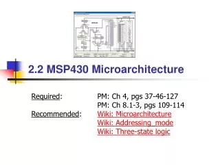
architectural overview: configuration ‘320 CPU Power FLL ROM RAM Watch ADC 12+2 bit JTAG MAB Bus conv. MDB 8 bit Timer Timer Port Basic Timer LCD I/O Port
16 bit 16 bit CPU register special register universal register R0 programm counter PC R4 universal register R1 stack pointer SP R5 universal register R2 statur register SR R6 universal register R3 const. generator CG2 R7 universal register R8 universal register R9 universal register R10 universal register R11 universal register R12 universal register R13 universal register R14 universal register R15 universal register
R0programm counter 15 1 0 0 16 bit 16 bit CPU register special register universal register R0 programm counter PC R4 universal register R1 stack pointer SP R5 universal register R2 statur register SR R6 universal register R3 const. generator CG2 R7 universal register R8 universal register R9 universal register R10 universal register R11 universal register R12 universal register R13 universal register R14 universal register R15 universal register
R1stack pointer 15 1 0 0 16 bit 16 bit CPU register special register universal register R0 programm counter PC R4 universal register R1 stack pointer SP R5 universal register R2 statur register SR R6 universal register R3 const. generator CG2 R7 universal register R8 universal register R9 universal register R10 universal register R11 universal register R12 universal register R13 universal register R14 universal register R15 universal register
R2 statur register SR R6 universal register R2status register R3 const. generator CG2 R7 universal register R8 universal register 15 9 8 7 6 5 4 3 2 1 0 VSCG1SCG0 OSCoffCPUoff GIEN Z C R9 universal register 16 bit 16 bit R10 universal register R11 universal register CPU register special register universal register R0 programm counter PC R4 universal register R1 stack pointer SP R5 universal register R12 universal register R13 universal register R14 universal register R15 universal register
formats of numbers 0 unsigned 0000h 65535 FFFFh 0001h 1 C + 49152 C000h 4000h 16384 7FFFh 32767 8000h 32768
formats of numbers 0 signed 0000h -1 FFFFh 0001h 1 - + -16384 C000h 4000h 16384 V 7FFFh 32767 8000h -32768
Flags Flags are set or cleared in dependence of logic or arithmetic instructions. Flags are used to control the program flow. Z-Flag (zero) set, if the result of a logic or arithmetic instruction is zero, otherwise cleared. N-Flag (negative) set, if the result of a logic or arithmetic instruction is negative, otherwise cleared. The N-Flag is a copy of the most significant bit (MSB)
Flags C-Flag (carry) set, if the result of a logic or arithmetic instruction produced a carry, otherwise cleared. V-Flag (overflow) set, if the result of an arithmetic instruction overflows the signed variable range, otherwise cleared. positiv + positive = negative negativ + negative = positive positive - negative = negative negative - positive = positive
CPU Power FLL ROM RAM Watch ADC 12+2 bit JTAG MAB Bus conv. MDB 8 bit Timer Timer Port Basic Timer LCD I/O Port memory configuration MSP430P325
memory model MSP430P325 Word accessByte access FFFFh FFE0h FFDFh C000h 03FFh 0200h 01FFh 0100h 00FFh 0010h 000Fh 0000h interrupt vectors 16 kB OTP OTP EPROM unused 512 Byte RAM 16 bit periphery RAM 8 bit periphery special function register
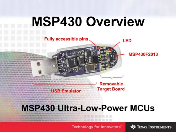
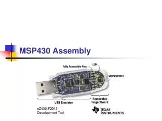
MSP430P325 starter kit The board
FFFFh FFE0h FFDFh EA00h C000h 03FFh 0200h 01FFh 0100h 00FFh 0010h 000Fh 0000h interrupt vectors monitor 16 kB OTP OTP EPROM unused 512 Byte RAM 16 bit periphery RAM 8 bit periphery special function register memory model MSP430P325 pre-programmed in starter kit
memory model MSP430P325 RAM-area in starter kit 3FEh 3E0h 3DFh 3DCh 214h 212h 200h interrupt vectors identification bit pattern stack used by application stack needed from monitor, 50 Bytes RAM user address range 3DCh - 214h (do not set the stack pointer) RAM-area for monitor
instruction set and addressing modes CPU Power FLL ROM RAM Watch ADC 12+2 bit JTAG MAB Bus conv. MDB 8 bit Timer Timer Port Basic Timer LCD I/O Port
instruction set • fifty-one instructions • twenty-seven basic instructions RISC • twenty-four emulated instructions CISC • byte and word processing • seven address modes for source • four address modes for destination • all instructions appropriate for all modules
instruction set - basic instructions Format I Format II Format III source,destination source or destination +/- 9bit offset ( Word ) ADD(.B) CALL JMP ADDC(.B) PUSH(.B) JC AND(.B) RETI JNC BIC(.B) RRA(.B) JEQ BIS(.B) RRC(.B) JNE BIT(.B) SWPB JGE CMP(.B) SXT JL DADD(.B) JN MOV(.B) SUB(.B) SUBC(.B) XOR(.B) 12 instructions 7 instructions 8 instructions 1 .. 6 cycles 1 .. 5 cycles 2 cycles 1 .. 3 word 1 .. 2 word 2 word
instruction set - emulated instructions • emulated instructions are: • basic instruction to the user • replaced with a basic instruction by the assembler • emulated instructions benefits: • increased processing speed • increased ROM code efficiency • supply users with familiar instructions • no additional effort in CPU: RISC with CISC-like instruction set
instruction set - emulated instructions Arithmetic Logical Data Program Flow ADC(.B ) INV(.B) CLR(.B) BR DADC(.B) RLA(.B) CLRC DINT DEC(.B) RLC(.B) CLRN EINT DECD(.B) CLRZ NOP INC(.B) POP(.B ) RET INCD(.B) SETC SBC(.B) SETN SETZ TST(.B) 7 instructions 3 instructions 9 instructions 5 instructions
instruction set - emulated instructions How to emulate instructions? emulated instruction basic instruction INC.B dst increment destination ADD.B #1,dst INCD.B dst double-incr. destination ADD.B #2,dst CLRN clear negative bit BIC #4,SR EINT enable interrupt BIS #8,SR INV dst invert destination XOR #0FFFFh,dst The trick is to take constant numbers in basic instructions by using special registers, the constant generators.
16 bit 16 bit CPU register special register universal register R0 programm counter PC R4 universal register R1 stack pointer SP R5 universal register R2 statur register SR R6 universal register R3constant register R3 const. generator CG2 R7 universal register R8 universal register Under different addressing modes: R9 universal register 15 0 R10 universal register 0 0 0 0 R11 universal register R12 universal register 0 0 0 1 R13 universal register R14 universal register 0 0 0 2 R15 universal register F F F F
16 bit CPU register special register universal register R0 programm counter PC R4 universal register R1 stack pointer SP R5 universal register R2 statur register SR R6 universal register R2status register R3 const. generator CG2 R7 universal register R8 universal register 15 9 8 7 6 5 4 3 2 1 0 VSCG1SCG0 OSCoffCPUoff GIEN Z C R9 universal register R10 universal register Under different addressing modes: R11 universal register R12 universal register 0 0 0 0 R13 universal register R14 universal register 0 0 0 4 R15 universal register 0 0 0 8
instruction set instruction table (example)
orthogonal instruction set • Orthogonality is, when all instructions with all address modes are valid for all operands • Orthogonality in MSP430… all single operand instructions use • all seven address modes. • and all double operand instructions use all seven source address modes and all four destination address modes
address modes • seven address modes for source • four address modes for destination mode source destination register mode indexed mode symbolic mode absolute mode indirect mode indirect autoincrement mode immediate mode
address modes register addressing mode ADD R7,R8 ; ( R7 ) + ( R8 ) ( R8 ) MOV R5,R6 ; ( R5 ) ( R6 ) CLR R5 ; #0 ( R5 ) XOR #1,R9 ; Toggle Bit 0 in R9 The operand is contained in one of the registers R0 to R15. This is the fastest addressing mode and needs the least memory .
address modes indexed addressing mode MOV 2(SP),R7 ; Move 2nd item of Stack to R7 MOV.B R5,9(R10) ; LSByte (R5) ((R10)+9) ADDC -2(R5),4(R7) ; ((R5)-2)+((R7)+4)+C ((R7)+4) The address of the operand is the sum of the index and the contents of the register. The indexed mode with index zero may used for “indirect register addressing” of the destination operand. BIS #8,0(R4) ; Set Bit 3 at address (R4)
address modes symbolic addressing mode (PC relative addressing) ADD EDE,TONI ; (EDE) + (TONI) (TONI) MOV TONI,EDE ; Move (TONI) to (EDE) MOV R5,TONI ; (R5) (TONI) MOV EDE,R8 ; (EDE) (R8) The content of the words EDE / TONI is used for the operation. Any address in the 64k memory space is addressable both as a source and as a destination.
address modes absolute addressing mode ADD &CCR1,&CCR2 ; (CCR1) + (CCR2) (CCR2) MOV &P1IN,&P2OUT ; Move (P1IN) to (P2OUT) MOV R5,&ACTL ; (R5) (ADC Control Register) MOV &TACTL,R8 ; (TACTL) (R8) The contents of the fixed addresses are used for the operation. Used for hardware peripheral modules that are located at an absolute address; used for Position Independent Code.
address modes indirect register addressing mode ADD @R8,R9 ; ((R8)) + (R9) (R9) MOV @R10,0(R12) ; ((R10)) ((R12)+0) MOV @R5,&ACTL ; ((R5)) (ADC Control Register) MOV.B @R4,R8 ; Byte addressed by R4 (R8) The registers are used as a pointer to the operand. The registers are not modified. Only for the source operand addressing.
address modes indirect register addressing with autoincrement ADD @R8+,R9 ; ((R8)) + (R9) (R9), (R8)+2 (R8) MOV @R10+,0(R12) ; ((R10)) ((R12)+0) , (R10)+2 (R10) MOV @R5+,&ACTL ; ((R5)) (ADC Register), (R5)+2 (R5) MOV.B @R4+,R8 ; Byte ((R4)) (R8) , (R4)+1 (R4) The registers are used as a pointer to the operand. The registers are incremented accordingly afterwards. Only for the source operand addressing.
address modes immediate register addressing mode BIT #0100h,4(R9) ; Test Bit 8=1 ? in the 3rd word of a table ; starting at (R9) MOV.B #01Fh,0(R12) ; 01Fh ((R12)+0) MOV #0010,&ACTL ; 0Ah (ADC Control Register) ADD #0A00h,R8 ; 0A00h + (R8) (R8) Any immediate 8 or 16 bit constant can be used with the instruction. Only for the source operand.
no yes no yes no yes stepsof softwaredevelopment start editor tools for software development assembler • editor • assembler • simulator • debugger success? simulator success? debugger (monitor) hardware success? end
softwaredevelopment source code line Label instruction operand(s) ; comment start mov #0FC17h, R15 ; load the ; value #0FC17h ; in register R15
softwaredevelopment assembler directives • .sect • .sect defines initialized named sction and associates subsequent code or data with this section example: .sect “INIT”,0214h • .set and .equ • .set and .equ directives set a constant value to symbol example: LCDCTL .equ 030h • .byte and .word • .byte places one or more 8-bit values into consecutive bytes of current section • .word places one or more 8-bit values into consecutive bytes of current section • .end • .end teminates assembly, should be the last source statement
programming techniques - stack and subroutines CPU Power FLL ROM RAM Watch ADC 12+2 bit JTAG MAB Bus conv. MDB 8 bit Timer Timer Port Basic Timer LCD I/O Port
stack and subroutine mainprogram mainprogram instruction A instruction A instruction B CALL subroutine instruction C instruction D instruction D CALL subroutine instruction B instruction E instruction C CALL subroutine instruction E instruction F instruction B CALL subroutine instruction C instruction G instruction F subroutine instruction B instruction B instruction C instruction C instruction G RETURN
low address register area memory stack R3 constant register stack stack area R2 flag register stack R1 stack pointer MP R0 program counter instruction A instruction B mainprogram instruction C instruction D instruction B instruction C No subroutine instruction E instruction B instruction C instruction F instruction B instruction C instruction G JMP MP high address stack and subroutine main process
low address high address stack and subroutine main process register area memory stack R3 constant register stack stack area R2 flag register stack R1 stack pointer MP R0 program counter instruction A instruction B mainprogram instruction C instruction D instruction B instruction C No subroutine instruction E instruction B instruction C instruction F instruction B instruction C instruction G JMP MP
low address high address stack and subroutine main process register area memory stack R3 constant register stack stack area R2 flag register stack R1 stack pointer MP R0 program counter instruction A instruction B mainprogram instruction C instruction D instruction B instruction C No subroutine instruction E instruction B instruction C instruction F instruction B instruction C instruction G JMP MP
low address high address stack and subroutine main process register area memory stack R3 constant register stack stack area R2 flag register stack R1 stack pointer MP R0 program counter instruction A instruction B mainprogram instruction C instruction D instruction B instruction C No subroutine instruction E instruction B instruction C instruction F instruction B instruction C instruction G JMP MP
low address high address stack and subroutine subroutine process register area memory stack R3 constant register stack stack area R2 flag register stack R1 stack pointer MP R0 program counter instruction A CALL SR mainprogram instruction D CALL SR instruction E CALL SR instruction F CALL SR instruction G JMP MP instruction B SR subroutine instruction C RET
stack and subroutine low address register area memory stack R3 constant register stack stack area R2 flag register stack R1 stack pointer MP R0 program counter instruction A CALL SR mainprogram instruction D CALL SR instruction E CALL SR instruction F CALL SR instruction G JMP MP instruction B SR subroutine instruction C RET high address subroutine process
low address high address stack and subroutine subroutine process register area memory stack R3 constant register stack stack area R2 flag register stack R1 stack pointer MP R0 program counter instruction A CALL SR mainprogram instruction D CALL SR instruction E CALL SR instruction F CALL SR instruction G JMP MP instruction B SR subroutine instruction C RET
low address high address stack and subroutine subroutine process register area memory stack R3 constant register stack address of instruction D stack area R2 flag register R1 stack pointer MP R0 program counter instruction A CALL SR mainprogram instruction D CALL SR instruction E CALL SR instruction F CALL SR instruction G JMP MP instruction B SR subroutine instruction C RET
low address high address stack and subroutine subroutine process register area memory stack R3 constant register stack Address of instruction D stack area R2 flag register R1 stack pointer MP R0 program counter instruction A CALL SR mainprogram instruction D CALL SR instruction E CALL SR instruction F CALL SR instruction G JMP MP instruction B SR subroutine instruction C RET
low address high address stack and subroutine subroutine process register area memory stack R3 constant register stack address of instruction D stack area R2 flag register R1 stack pointer MP R0 program counter instruction A CALL SR mainprogram instruction D CALL SR instruction E CALL SR instruction F CALL SR instruction G JMP MP instruction B SR subroutine instruction C RET