Download
1 / 44
450 likes | 571 Views
EECS 122: Introduction to Computer Networks Packet Scheduling and QoS. Computer Science Division Department of Electrical Engineering and Computer Sciences University of California, Berkeley Berkeley, CA 94720-1776. Today’s Lecture: 15. 2. 17, 18, 19. Application. 10,11. 6. Transport.

E N D
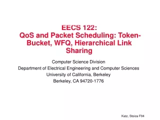
EECS 122: Introduction to Computer Networks Packet Scheduling and QoS Computer Science Division Department of Electrical Engineering and Computer Sciences University of California, Berkeley Berkeley, CA 94720-1776
Today’s Lecture: 15 2 17, 18, 19 Application 10,11 6 Transport 14, 15, 16 7, 8, 9 Network (IP) 21, 22, 23 Link Physical 25
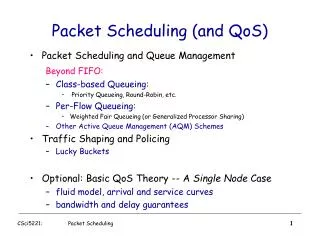
Packet Scheduling • Decide when and what packet to send on output link • Usually implemented at output interface of a router flow 1 Classifier flow 2 Scheduler 1 2 flow n Buffer management
Goals of Packet Scheduling • Provide per flow/aggregate QoS guarantees in terms of delay and bandwidth • Provide per flow/aggregate protection • Flow/Aggregate identified by a subset of following fields in the packet header • source/destination IP address (32 bits) • source/destination port number (16 bits) • protocol type (8 bits) • type of service (8 bits) • Examples: • All packets from machine A to machine B • All packets from Berkeley • All packets between Berkeley and MIT • All TCP packets from EECS-Berkeley
Outline • QoS guarantees • Link sharing • Service curve (short)
Recap: Token Bucket and Arrival Curve • Parameters • r – average rate, i.e., rate at which tokens fill the bucket • b – bucket depth • R – maximum link capacity or peak rate (optional parameter) • A bit is transmitted only when there is an available token • Arrival curve – maximum number of bits transmitted within an interval of time of size t Arrival curve r bps bits slope r b*R/(R-r) b bits slope R <= R bps time regulator
How Is the Token Bucket Used? • Can be enforced by • End-hosts (e.g., cable modems) • Routers (e.g., ingress routers in a Diffserv domain) • Can be used to characterize the traffic sent by an end-host
Source Traffic Characterization • Arrival curve – maximum amount of bits transmitted during an interval of time Δt • Use token bucket to bound the arrival curve bps bits Arrival curve Δt time
(R=2,b=1,r=1) Source Traffic Characterization: Example • Arrival curve – maximum amount of bits transmitted during an interval of time Δt • Use token bucket to bound the arrival curve Arrival curve bits 4 bps 3 2 2 1 1 Δt 0 1 2 3 4 5 1 2 3 4 5 time
QoS Guarantees: Per-hop Reservation • End-host: specify • the arrival rate characterized by token-bucket with parameters (b,r,R) • the maximum maximum admissible delay D • Router: allocate bandwidth ra and buffer space Ba such that • no packet is dropped • no packet experiences a delay larger than D slope ra slope r bits Arrival curve b*R/(R-r) D Ba
Packet Scheduling • Make sure that at any time the flow receives at least the allocated rate ra • The canonical example of such scheduler: Weighted Fair Queueing (WFQ)
Recap: Fair Queueing • Implements max-min fairness: each flow receives min(ri, f) , where • ri– flow arrival rate • f – link fair rate (see next slide) • Weighted Fair Queueing (WFQ) – associate a weight with each flow
Fair Rate Computation: Example 1 • If link congested, compute f such that f = 4: min(8, 4) = 4 min(6, 4) = 4 min(2, 4) = 2 8 10 4 6 4 2 2
Flow i is guaranteed to be allocated a rate >= wi*C/(Σk wk) If Σk wk <= C, flow i is guaranteed to be allocated a rate >= wi Fair Rate Computation: Example 2 • Associate a weight wiwith each flow i • If link congested, compute f such that f = 2: min(8, 2*3) = 6 min(6, 2*1) = 2 min(2, 2*1) = 2 8 (w1 = 3) 10 4 6 (w2 = 1) 4 2 2 (w3 = 1)
Fluid Flow System • Flows can be served one bit at a time • WFQ can be implemented using bit-by-bit weighted round robin • During each round from each flow that has data to send, send a number of bits equal to the flow’s weight
Fluid Flow System: Example 1 Flow 1 (w1 = 1) 100 Kbps Flow 2 (w2 = 1) Flow 1 (arrival traffic) 1 2 4 5 3 time Flow 2 (arrival traffic) 1 2 3 4 5 6 time Service in fluid flow system 3 4 5 1 2 1 2 3 4 5 6 time (ms) 0 10 20 30 40 50 60 70 80
Fluid Flow System: Example 2 link • Red flow has packets backlogged between time 0 and 10 • Backlogged flow flow’s queue not empty • Other flows have packets continuously backlogged • All packets have the same size flows weights 5 1 1 1 1 1 0 2 4 6 8 10 15
Implementation In Packet System • Packet (Real) system: packet transmission cannot be preempted. Why? • Solution: serve packets in the order in which they would have finished being transmitted in the fluid flow system
Select the first packet that finishes in the fluid flow system Packet System: Example 1 Service in fluid flow system 3 4 5 1 2 1 2 3 4 5 6 time (ms) Packet system 1 2 1 3 2 3 4 4 5 5 6 time
Select the first packet that finishes in the fluid flow system Packet System: Example 2 Service in fluid flow system 0 2 4 6 8 10 Packet system 0 2 4 6 8 10
Implementation Challenge • Need to compute the finish time of a packet in the fluid flow system… • … but the finish time may change as new packets arrive! • Need to update the finish times of all packets that are in service in the fluid flow system when a new packet arrives • But this is very expensive; a high speed router may need to handle hundred of thousands of flows!
Finish times computed at time 0 time 0 1 2 3 Finish times re-computed at time ε time 0 1 2 3 4 Example • Four flows, each with weight 1 Flow 1 time Flow 2 time Flow 3 time Flow 4 time ε
Solution: Virtual Time • Key Observation: while the finish times of packets may change when a new packet arrives, the order in which packets finish doesn’t! • Only the order is important for scheduling • Solution: instead of the packet finish time maintain the number of rounds needed to send the remaining bits of the packet (virtual finishing time) • Virtual finishing time doesn’t change when the packet arrives • System virtual time – index of the round in the bit-by-bit round robin scheme
System Virtual Time: V(t) • Measure service, instead of time • V(t) slope – normalized rate at which every backlogged flow receives service in the fluid flow system • C – link capacity • N(t) – total weight of backlogged flows in fluid flow system at time t V(t) time Service in fluid flow system 1 2 3 4 5 6 1 2 3 4 5 time
System Virtual Time (V(t)): Example 1 • V(t) increases inversely proportionally to the sum of the weights of the backlogged flows Flow 1 (w1 = 1) time Flow 2 (w2 = 1) time 3 4 5 1 2 1 2 3 4 5 6 V(t) C/2 C
System Virtual Time: Example w1 = 4 w2 = 1 w3 =1 w4 =1 w5 =1 V(t) C/4 C/8 C/4 0 4 8 12 16
Fair Queueing Implementation • Define • - virtual finishing time of packet k of flow i • - arrival time of packet k of flow i • - length of packet k of flow i • wi – weight of flow i • The finishing time of packet k+1 of flow i is / wi
Properties of WFQ • Guarantee that any packet is transmitted within packet_lengt/link_capacity of its transmission time in the fluid flow system • Can be used to provide guaranteed services • Achieve max-min fair allocation • Can be used to protect well-behaved flows against malicious flows
Outline • QoS guarantees • Link sharing • Service curve (short)
Hierarchical Link Sharing 155 Mbps Link 55 Mbps 100 Mbps Provider 1 Provider 2 50 Mbps 50 Mbps Berkeley Stanford. • Resource contention/sharing at different levels • Resource management policies should be set at different levels, by different entities • Resource owner • Service providers • Organizations • Applications 20 Mbps 10 Mbps Math Campus EECS seminar video seminar audio WEB
Hierarchical WFQ (H-WFQ) Example 10 • Red session has packets backlogged at time 5 • Other sessions have packets continuously backlogged 5 1 1 1 1 1 4 1 First red packet arrives at 5 …and it is served at 7.5 Service in fluid flow system 0 10 20
Packet Approximation of H-WFQ • Idea 1 • Select packet finishing first in H-WFQ assuming there are no future arrivals • Problem: • Finish order in system dependent on future arrivals • Virtual time implementation won’t work • Idea 2 • Use a hierarchy of WFQ to approximate H-WFQ Fluid Flow H-WFQ Packetized H-WFQ 10 10 WFQ WFQ 6 4 6 4 WFQ WFQ WFQ WFQ 1 1 3 3 2 2 WFQ WFQ WFQ WFQ WFQ WFQ
Problems with Idea 1 10 • The order of the 4th blue packet finish time and of the first green packet finish time changes as a result of a red packet arrival 5 1 1 1 1 1 Green packet finish first 4 1 Make decision here Blue packet finish first
Problem with Idea 2 10 • A packet on the second level can miss its deadline (finish time) 5 1 1 1 1 1 4 1 First level packet schedule Second level packet schedule First red packet arrives at 5 …but it is served at 11 !
Solution • Hierarchical-WFQ with a better implementation of WFQ, called Worst-Case Weighted Fair Queueing (WF2Q) • Main idea of WF2Q • Consider for scheduling only eligible packets • Eligible packet at time t: a packet that has started being serviced in the fluid flow system at time t
Example Fluid-Flow System WFQ (smallest finish time first) WF2Q (smallest eligible finish time first)
Hierarchical-WF2Q Example 10 • In WF2Q, all packets meet their deadlines modulo time to transmit a packet (at the line speed) at each level 5 1 1 1 1 1 4 1 First level packet schedule Second level packet schedule First red packet arrives at 5 ..and it is served at 7
Outline • QoS guarantees • Link sharing • Service curve (short)
Bandwidth-Delay Coupling • Assume • An arrival curve specified by token bucket (R, r, b) • A reservation request (rmin, D), where rmin – minimum bandwidth, D – maximum delay • WFQ can be inefficient: to satisfy delay D, the allocated rate ra may need to be much higher than r ! slope ra slope r bits Arrival curve b*R/(R-r) D
Example • End-host: request a worst-case delay D=10ms for a flow characterized by token bucket (R=1Mbps, b=10Kb, r=100Kbps) • Router: allocate rate ra, where • Thus, the router needs to allocate to the flow more than 5 times its average rate r ! ra = b*R / (D*(R-r) + b) = 0.52Mbps
WFQ implements a linear service curve Solution: Service Curve • Generalize the service allocated to a flow • Assume a flow that is idle at time s and it is backlogged during the interval (s, t) • Service curve: the minimum service received by the flow during the interval (s, t) bits Arrival Curve D B S(t) = service curve t
Video packets have to wait after ftp packets Linear Service Curves: Example bits bits Service curves FTP Video t t Arrival process bits bits Arrival traffic t t bits bits Service t t t
Video packets transmitted as soon as they arrive Non-Linear Service Curves: Example bits bits Service curves FTP Video t t Arrival process bits bits Arrival traffic t t bits bits Service t t t
What You Need to Know • Basic concepts • Arrival & service curve • Token-bucket specification • System virtual time / finish virtual time • WFQ properties • Link sharing requirements and challenges • Bandwidth-delay coupling problem • Mechanisms: • WFQ implementation in the fluid flow & packet system • You don’t need to know • Details of WF2Q • How service curve works