Download
1 / 35
360 likes | 499 Views
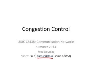
Congestion Control Algorithm. Preallocation of Buffers e.g., Allocate Buffer to Each Virtual Circuit in Each IMP. Note: This May be Expensive, and Only Used Where Low Delay & High Bandwidth are Essential ( e.g. , Digitized Voice). Packet Discarding.

E N D
Congestion Control Algorithm • Preallocation of Buffers e.g., • Allocate Buffer to Each Virtual Circuit in Each IMP. Note: This May be Expensive, and Only Used Where Low Delay & High Bandwidth are Essential (e.g., Digitized Voice)
Packet Discarding • Datagram Service: Packet Discard at Will • Virtual Circuit Service: A Copy of Packet Must be Kept Note: If Congestion is to be Avoided by Discarding Packets, A Rule is Needed Input Lines Output Lines Free Buffer Congestion can be reduced by putting an upper bound on the number of buffers queued on an output file
Packet Discarding (cont.) (Irland) Discovered Simple Rule of Thumb (Not Optimal) for Determining Max Q Length, m, for an IMP With k Buffers m = k / Ö s, Where sº # of Output Lines
Internetworking • Many Different Networks Exist • Different Networks Have Radically Different Technology • Still Desirable to Connect These Networks Examples of This Follow: 1. LAN-LAN: A Computer Scientist Downloading a File to Engineering 2. LAN-WAN: A Computer Scientist Sending Mail to a Distant Physicist 3. WAN-WAN: Two poets Exchanging Sonnets 4. LAN-WAN-LAN: Engineers at Different Universities Communicating
Four Common Types of Relays • Layer 1: Repeaters Copy Individual Bits Between Cable Segments • Layer 2: Bridges Store and Forward Frames Between LANs • Layer 3: Gateways Store and Forward Packets Between Dissimilar Networks • Layer 4: Protocol Converters Provide Interfacing in Higher Layers
The boxes marked B are bridges. Those marked G are gateways. Network interconnection
Gateways Operate at The Network Level Two Styles: • Connection-Oriented e.g., Virtual Circuit • Connectionless-Oriented e.g., Datagram
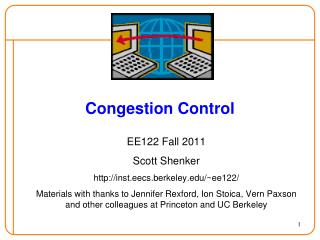
Internetworking(A Full Gateway) Network 1 Network 2 B U F F E R Net 1 to Internet Internet to Net 1 Net 2 to Internet Internet to Net 2 1 2 Machine owned jointly by both network
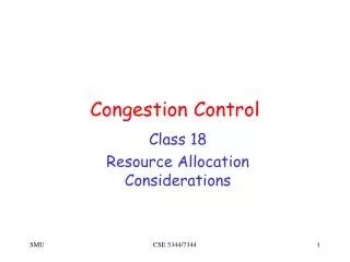
Internetworking(Two half-Gateways) Communication Line Network 1 Network 2 Net 1 to Internet Internet to Net 1 Net 2 to Internet Internet to Net 2 1 2 Machine owned by Network 1 Machine owned by Network 2
Source Host Destination Host Networks Gateway (a) Internetworking using concatenated virtual circuits The Network Layer
Source Host Destination Host (b) Internetworking using datagrams The Network Layer (cont)
A datagram moving fromnetwork to network (cont.) DHX: Data link Header for network X DTX: Data link Trailer for network X IP : Internet Protocol header TH : Transport Header Frame 1 DH1 IP TH DT1 Frame 2 DH2 IP TH DT2 Frame 3 DH3 IP TH DT3 Internet packet
Network 2 Network 1 Packet G1 fragments a large packet G2 reassembles the fragment G3 fragments again G4 reassembles again Transparent Fragmentation
Packet G1 fragments a large packet The fragments are not reassembled until the final destination (a host) is reached Non-transparent Fragmentation
Firewall • A dedicated gateway machine with special security precautions on it. • Out-going/in-coming packets may be blocked. • IP address and a port number may be used to block the packets.
The IP Protocol 32 Bits Version IHL Type of Service Total Length D F Identification Fragment Offset M F Header Checksum Time to Live Protocol Source Address Destination Address Options (0 or more words) The IP (Internet Protocol) header
The IP Addresses 32 Bits Range of host address Class 1.0.0.0 to 127.255.255.255 0 Network A Host 128.0.0.0 to 191.255.255.255 10 Network B Host 192.0.0.0 to 223.255.255.255 110 Network C Host 224.0.0.0 to 239.255.255.255 1110 D Multicast Address 240.0.0.0 to 247.255.255.255 11110 E Reserved for Future use IP address formats
0 0 0 0 0 0 0 0 0 0 0 0 0 0 0 0 0 0 0 0 0 0 0 0 0 0 0 0 0 0 0 0 This host 0 0 … 0 0 A host on this network Host Broadcast on the local network 1 1 1 1 1 1 1 1 1 1 1 1 1 1 1 1 1 1 1 1 1 1 1 1 1 1 1 1 1 1 1 1 Broadcast on the distant network Network 1 1 1 1 … 1 1 1 1 127 (Anything) Loopback Special IP addresses The IP Addresses
32 Bits Host 1 0 Network Subnet Subnet mask 1 1 1 1 1 1 1 1 1 1 1 1 1 1 1 1 1 1 1 1 1 1 0 0 0 0 0 0 0 0 0 0 One of the ways to subnet a class B network The IP Addresses
32-bit Internet Addr ARP RARP 48-bit Ethernet Addr ARP Provides a mapping between the two forms of addresses: 32-bit IP addresses and data link addresses (e.g., 48-bit Ethernet addr.)
V W X Z Y V W X Z Y V W X Z Y ARP Request/Reply
ARP (cont’d) Fund. Concept: The network interface has a hardware address, and frames exchanged at the hardware level must be addressed to the correct interface. TCP/IP works with its own addresses (i.e., 32-bit IP addresses). Knowing a host’s IP addresses does not let the kernel (i.e., Ethernet driver) must know the hardware address to send the data.
Summary Protocol addresses cannot be used when transmitting frames across physical network hardware, because the hardware does not understand IP addressing. So, a frame sent across a given physical network must use hard ware’s frame format, and all addresses in the frame must be hardware address
Router has 2IP addresses Router has 2IP addresses To WAN 192.31.60.4 192.31.60.7 192.31.65.1 192.31.63.3 192.31.65.7 192.31.65.5 192.31.63.8 F2 1 2 3 4 F1 F3 Ethernet addresses E1 E2 E3 E4 E5 E6 CS Ethernet 192.31.65.0 Campus FDDI ring 192.31.60.0 EE Ethernet 192.31.63.0 Three interconnected class C networks: two Ethernets and an FDDI ring
Internet Control Protocols • ICMP (Internet Control Message Protocol) • ARP (Address Resolution Protocol) • RARP (Reverse Address Resolution Protocol) • BOOTP (Bootstrap Protocol)
BOOTP (cont’d) BOOTP uses UDP and is intended as an alternative to RARP For bootstrapping a diskless system to find its IP address. Bootp can also return additional information such as the IP address of a router, the client’s subnet mask, and the IP address of a name server.
BOOTP (cont’d) BOOTP DHCP (Dynamic Host Configuration Protocol) Unlike BOOTP, DHCP does not require an administrator to add an entry for each computer to the database that a server uses. Instead, DHCP provides a mechanism that allows a computer to join a new network and obtain an IP address without manual intervention. Note: An administrator can configure a DHCP server to have 2 types of addresses: Permanent addresses and a pool of addresses to be allocated on demand.
Operation of ARP (2) (3) FTP TCP IP establish connection with IP address send IP datagram to IP address (4) Host Name IP addr (1) Resolver ARP (5) (6) (8) (9) Ethernet Driver ARP request (Ethernet broadcast) Ethernet Driver Ethernet Driver (7) ARP ARP IP TCP Operation of ARP when user types “ftp hostname”
Goals: IPv6 • Support billions of hosts, even with inefficient address space allocation • Reduce the size of the routing tables • Simplify the protocol, to allow routers to process packets faster • Provide better security (authentication and privacy) than current IP • Pay more attention to type of service, particularly for real-time data
IPv6 (cont’d) • Aid multicasting by allowing scopes to be specified • Make it possible for a host to roam without changing its address • Allow the protocol to evolve in the future • Permit the old and new protocols to coexist for years
32 Bits Version Priority Flow label Next header Payload length Hop limit Source address (16 bytes) Destination address (16 bytes) The IPv6 fixed header (required)
Examples of The Network Layer 7 6 5 4 3 2 1 7 6 5 4 3 2 1 Application protocol (not defined by X.25) Presentation protocol (not defined by X.25) Session protocol (not defined by X.25) Transport protocol (not defined by X.25) X.25 layer 3 X.25 layer 3 3 2 1 3 2 1 3 2 1 X.25 layer 2 X.25 layer 2 X.25 layer 1 X.25 layer 1 DTE DTE Internal protocols are not defined by X.25 The place of X.25 in the protocol hierarchy
Two Forms of Connections • Virtual Calls --- A Connection is Established, Data Are Transferred, & Then The Connection is Released • Permanent Virtual Calls --- Like A Leased Line, DTE at Either End LAN Just Send Data Whenever It Wants, Without Any Setup • Note: The Choice of Circuit # on Outgoing Calls is Determined by The DTE, and on Incoming Calls by The DCE, May Lead to A Call Collision.
The Three Phases of an X.25 connection