Download
1 / 107
1.08k likes | 1.39k Views
E lectronic A rticle S urveillance. AMS-9040 U ltra C ontroller. Ultra•Max Acousto-Magnetic Technology. Revised April, 2006. Rev. C. Training Overview. Goal

E N D
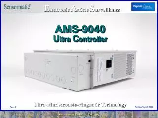
Electronic Article Surveillance AMS-9040 Ultra Controller Ultra•Max Acousto-Magnetic Technology Revised April, 2006 Rev. C
Training Overview • Goal • The Goal of this training is to provide the service technician with the necessary skills to install, configure, and adjust the AMS-9040 system so that it performs to a level expected by the customer. • Products • This training Includes the AMS-9040 controller, associated system detectors, and the Service Configurator program.
Training Overview • Description • This course consists of a combination of lecture, demonstration, and follow on lab with an estimated length of 5-6 hours. • Prerequisite • Prior Ultra•Max EAS experience • ADS-216 Controller or AMS-9030 Controller
Training Objectives (cont.) • Upon completion of this training, using the service documentation, you should be able to: 1. Describe the major components that make up an AMS-9040 EAS System. 2. Identify and describe the various types of antennas and pedestals that can be used by the AMS-9040 controller. 3. Describe the capabilities and limitations of any supported system configuration. 4. Locate and describe the function of each connector in the AMS-9040 Controller. 5. Install the AMS-9040 controller and make all necessary connections to power source, antennas, and alarm units.
Training Objectives 6. Using the ADS4 configurator, configure the 9040 controller to operate with any supported pedestal and antenna combinations. 7. Resonate transmitters and set adjustment for proper current. • Using the ADS4 configurator, monitor environment noise and configure and adjust receivers for best possible performance. • Download voice files to the antennas or to the Digital Remote alarm unit. • Using the ADS4 configurator, identify phasing issues and adjust phasing if necessary. 11. Using the ADS4 configurator, isolate a hardware malfunction to a replaceable component. 12. Update controller and antenna firmware when necessary.
Introduction • AMS-9040 Controller is the latest generation, 4-channel design. • New electronics will expand the number of digital antennas that can be connected to a single controller to four. • Worldwide compatible* • Replaces today’s two-controller configurations with a single controller (at a comparable cost). • Move some antenna unique electronics from the controller to the antenna capacitor boards (reduces controller cost). * Note - with some restrictions in certain countries
Introduction • Supported Antennas • Digital ProMax IV • Digital FloorMax IV • Digital DoorMax IV • Digital Euro ProMax IV • AMS-3000 Loop • AMS-3003 Extended Loop • AMS-3010 Wide Exit Loop (9040 Loops are non European only) • Auxiliary Receivers Ranger SkyMax Mullion mount • Antennas Not Supported • EuroMax Plus • ProMax Plus • FloorMax (old) • FloorMax Plus • UltraPost Secondary
Introduction • Design Features • Drive up to 4 XCVR Antennas • Drive up to 4 Aux Receivers/Noise canceling antennas • Drive up to two Remote Alarms • Drive up to two Beacon Lamps • Conduit Ready • Single Printed Circuit Board (PCB) • RS-485 interface • RS-232 Service Port • New antenna / peripheral architecture • New Digital Signal Processor (DSP) chip (TI), higher integration of DSP/receiver electronics • Configurator Required for Installation (New Configurator) • Similar in size and weight than the ADS-216 controller • The four transmitter channels can be multiplexed to eight antenna coils (typically four pedestals).
Introduction • Digital Antennas • Same antennas with newcapacitortuningboards • Each antenna now has an address selection switch which identifies its unique address • The alarm circuits are driven from the pedestal • Remaining Functions are the same as the D216 antennas • Assisted Transmitter Tuning • Service port at antennas • Antenna ID (Identifies Cap Board Type) • Key Switch to control the Alarms and the Tx
Introduction • New Capacitor Board Advantages • Independent alarm control of antennas • Zone Identification now possible • Supports different message per pedestal • Software on antennas now flash upgradeable • Higher noise immunity & higher data rates • Longer alarm messages with higher dynamic range Note - New pedestal is incompatible with existing digital antennas Capacitor Board.
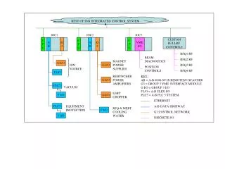
RS485 to RS232 converter to Modem (BB Electronics Model #485SD9TB) Or RS485 to Ethernet converter for Networking (Lantronix Model #UDS10 converter) System Network RS-485 RS-485 Peripheral Network Networks • AMS-9040 System and Peripheral Networks
J2: RS232/ Laptop interface Single Printed Circuit Board (PCB) J5: Sync Link DS1: Status LED/Heartbeat Cable Housing / Mounting Bracket AC Power SwitchRocker Switch or Optional Key Switch Conduit openings for AC Power Mechanical Description • 9040 Chassis Assembly
Tx Current Sense & Sequencer AC Input/EMI Filter DSP /ReceiverCircuits Transmitter Power Ampsand High Voltage Supply Low Voltage Supply Mechanical Description • PCB: Major Functional Blocks
PCB Connectors 4 Receive-Only Aux Ports Antenna Comm Ports 4 Tx/Rx Ports Comm port connections should correspond to TX/RX connections (A-A, B-B etc). P1 P24 P4 P35 Aux A C P5 P25 P6 P36 A B C D A B C D B D 9040 Controller Connectors
P41 UltraLink Power (1) ….P7 Remote Alarms (2) P10 Beacon Lamps (2) The 9040 can power no more than 2 remote alarms, 2 beacon lamps and 1 Ultra Link. P3: AC Input P8: RS485 P26: Pedestal Inhibit P9: Relays 1 & 2 P12: Relays 3 & 4 P2: Wired Sync Fan P13: Fan Conn. DS1: Status LED /Heartbeat J5: Sync Link J2: RS232 (Laptop interface) 9040 Controller Connectors • PCB (cont.)
9040 Controller Description • 9040 Transmitters - Simultaneous Transmit of Two Antennas (4 Coils) - Antennas A & C are multiplexed and Antennas B & D are multiplexed.(Similar to M4K) - 2 Antennas Antennas A and B will transmit simultaneously - 4 Antennas Antennas A and B will transmit simultaneously,then antennas C and D will transmit simultaneously - 3 Antennas A and B transmit simultaneously, then B and C will transmit simultaneously
9040 Controller Description • 9040 Receivers: • The 9040 has eight Rx Channels • In normal Rx Configuration (phase flipping), one pedestal utilizes one Rx Channel. • If “nulling” or “coil 1-2” configuration is selected, the pedestal will utilize two Rx Channels. • Therefore, if you have Aux receivers or noise canceling coils associated with Pedestals A and B, you will want to connect the Rx-only antennas to Aux C and/or Aux D, rather than to Aux A and/or Aux BIf you use Aux A and B, It functions, but the system will be slowed down
Installation • Installation Steps • Install Controller • Install Antennas • Install Alarm Units • Make Connections • Set Antenna Addresses (New Step) • Configure (Zone Mapping) (New Step) • Tuning and Testing
Top Cover Cable Tray/mounting bracket Controller Installation • Installing Controller • Remove Top Cover and Cable Tray/Mounting Bracketfrom Controller
Installation • Installing Controller (cont.) • Remove knockouts closest to connectors they are associated with - Class 2 Dry for Remote Alarms - Class 2 Wet for AlarmManagement device - Class 3 for Antennas • Attach Conduit and/or Cables Cable Tray / Mounting Bracket
Installation • Installing Controller (cont.) • Mount Cable tray/mounting bracket to: - Wall - Ceiling - Shelf Wall Ceiling Shelf
OK Not OK Installation • Installing Controller (cont.) • Wall Mounting Warning - Mounting Bracket can only be mounted facing up or with cable entry to the left, as shown.
Installation • Installing Controller (cont.) • Mount Controller partially onto the mounting bracket, route cables through rectangular opening in the controller housing, attach connectors, and plug connectors into board.
Installation • Installing Controller (cont.) • Hardwire AC Cable or attach Power Cord
Installation • Installing Controller (cont.) • Slide Controller completely onto the mounting bracket and secure the two 1/4 turn fasteners
Antenna DCap Board Antenna CCap Board Antenna BCap Board Antenna ACap Board P1 P24 P4 P35TXRX A TXRX B TXRXC RXRX D Installing Digital 4 Antennas • Connect Tx/Rx cables to Power Pack • Install Romex-Type connectors or conduit fittings in knockouts • Route each Tx/Rx cable through knockout (locations on bracket) • Plug into appropriate TXRX connector on controller board(This connection determines which antenna is which (A,B,C,D) and also sets the address requirements for each cap board. (0,1,2,3)) 9040Controller Board
COM A COM B COM C COM D RS485 P5 P25 P6 P36 P8 Wired Sync Relay 3 & 4 Relay 1 & 2 PED Inh. P2 P12 P9 P26 AMS-9040 Controller Connecting Conduit and Cables • Connect Com cables to Power Pack • Route each Com cable through knockout • Using a small screwdriver, attach Connectors 2109-0510-10 to each Com cable following the color coded label.
9040 Controller Description • Antenna Addressing • The antenna addresses range from 0 to 7. • The antenna cap board address must be set to match the connector that its attached to. • Ex. The cap board that is attached TX/RX A, must be set to address 0 • Duplicate address are not allowed • The 9040 can support up to eight addressable antennas • If more than four are used, two Comm Cables can be terminated to a single Comm port.
DoorMax and Euro ProMax Cap Board • Assisted Tuning is like D216, except only one coil is tuned at a time • If DS1 and DS2 are on, set JW1-5 to correspond to Tuning LEDs then Press Button • If DS1 and DS3 are on, set JW6-10 to correspond to Tuning LEDs then press button • Repeat until Tx Off LED remains off
FloorMax Cap Board • Assisted Tuning is like D216, except only one coil is tuned at a time • If DS1 and DS2 are on, set Left Bank jumpers to correspond to Tuning LEDs then Press Button • If DS1 and DS3 are on, set Right Bank jumpers to correspond to Tuning LEDs then press button • Repeat until Tx Off LED remains off
ProMax Cap Board Description • Assisted Tuning is like D216, except only one coil is tuned at a time • If DS1 and DS2 are on, set Bottom coil jumper to correspond to Tuning LEDs then Press Button • If DS1 and DS3 are on, set Top coil jumpers to correspond to Tuning LEDs then press button • Repeat until Tx Off LED remains off
Installing Digital 4 Pedestals • For each pedestal, connect the Tx/Rx (4-conductor) and Com (9-conductor) cables to the capacitor board. • Using a small screwdriver, attach the TX/Rx cable to connector 2109-0254-04 according to the following: Pin 1-Black Pin2-Red Pin 3-Green Pin 4-White Pin 5-Shield • Insert connector 2109-0254-04 into pluggable terminal block P1 on the capacitor board Tx/Rx P1
Installing Digital 4 Pedestals • Using a small screwdriver, attach the Com cable to connector 2109-0510-10 following the color-coded label:Pin 1-Black Pin 2-Brown Pin 3-Red Pin 4-Orange Pin 5-Yellow Pin 6-Green Pin7-Blue Pin 8-Violet Pin 9-Gray Pin 10-Shield • Insert connector 2109-0510-01 into P6 on Cap board P6Com Cable
Connecting Conduit and Cables • Set Antenna Addresses • Ped A Cap Board to 0 • Ped B Cap Board to 1 • Ped C Cap Board to 2 • Ped D Cap Board to 3 Selectable from 0 to 7On Cap Board
Pedestal Tuning • The antenna is shipped with the jumpers set to default settings that are acceptable for most installations. However, the antenna may require tuning to adjust for conditions at the installation site. • To tune the pedestal, do the following: • Turn off power pack • Make sure P10(in all Digital 4 antennas) is removed when the pedestal connected to AMS-9040 controller • Access the capacitor board in the enclosure • Make sure that the jumpers are set to defaults.
Pedestal Tuning • Turn On power pack • Beginning with Antenna A, check the green Tx Off LED on the capacitor board for each antenna. • If the green Tx Off LED is off, the antenna is tuned. • If the green Tx Off LED is on, the antenna needs tuning. • The antenna is tuned by changing jumper settings on the capacitor board. The controller assists tuning by lighting LED's to indicate the correct jumper settings.
Pedestal Tuning • Step 1 • When DS2 is on indicates the tuning setting is for the Bottom coil (left bank) • Set the jumpers JW1-JW7 per the DS4-DS10 respectively • Next, depress check tuning button
Pedestal Tuning • Step 2 • When DS3 is on indicates the tuning setting is for the Top coil (right bank) • Set the jumpers JW8-JW14 per the DS4-DS10 respectively • Next, depress check tuning button • Repeat Step 1 and 2 Until DS1 is off
WARNING—RISK OF ELECTRIC SHOCK! The green Tx Off LED on the capacitor board must be ON before changing jumpers. It indicates there are no high voltages on the board. Pedestal Tuning • Change the jumpers on the capacitor board to the settings indicated by the yellow LED's on the capacitor board. • If a yellow jumper LED is on, place the corresponding jumper in the “In” (1-2) position. • If a yellow jumper LED is off, place the corresponding jumper in the “Out” (2-3) position.
Pedestal Tuning • Press the check tuning button on the capacitor board and return to previous step and change jumpers again to match LED's • After repeating these two steps several times, the antenna should be tuned with all yellow LED's off except DS3 will be flashing one second on and one second off to indicate normal operation. • After repeating step 1 and 2 eight times the yellow LED's flash five times, this mean the pedestal did not tuned to the max current and pedestal cannot be tuned. Turn off the power pack and check cable connections and antenna coil connections • Repeat the above tuning procedures to all the antennas
Basic Operation • Detection Processing • The detection processing consists of determining whether eight criteria have passed: • Signal-to-noise ratio (diversity combined tag signals exceeds the threshold) • Frequency Mean • Frequency Range • Demod. Amp • Demod. Phase • Q Amp • Q Phase • SNR Noncoh. • If all of these conditions have been met, the alarm is activated.
Basic Operation • Transmitter / Receiver Sequence (1 time slot)
Basic Theory of Operation • Decision Sequence- No more Validation state - Performs Continuous Validation
Installation Considerations • European Applications,Click here Non-European Applications,Continue with next slide
Configurations The following configurations and restrictions are for Non-European applications only
Application Requirements • Pedestals • Transmitters operate at 16 amps, Phase Flipping • Pedestals A and B firing simultaneous-alternating • Pedestals C and D firing simultaneous-alternating • FloorMax Antennas • Transmitters operate at 16 amps, Phase Flipping • Antennas must be installed so that adjacent antennas donot fire simultaneously • The installed order of the antennas across the exit must be: • A - C for two antennas • A - C - B for three antennas • A - C - B - D for four antennas
Application Requirements • Loop Antennas • Systems have transmitter current limitations. • Refer to the antenna installation guides.