Download
1 / 28
280 likes | 303 Views
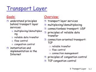
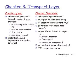
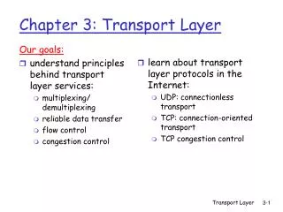
The Transport Layer Congestion Control & UDP. Chapter 6. Congestion Control. Desirable bandwidth allocation Regulating the sending rate. Desirable Bandwidth Allocation (1). (a) Goodput and (b) D elay as a function of offered load. Desirable Bandwidth Allocation (2).

E N D
Congestion Control • Desirable bandwidth allocation • Regulating the sending rate
Desirable Bandwidth Allocation (1) (a) Goodput and (b) Delay as a function of offered load
Desirable Bandwidth Allocation (2) • Best network performance when bandwidth is allocated up to when delay shoots up. • Power: Power = Load / Delay • Power rises initially with load. • Reaches maximum and falls when delay grows rapidly. • Load with highest power – efficient load.
Desirable Bandwidth Allocation (3) • Notion of max-min fairness. • B/w given to one flow can’t be increased without decreasing b/w for another flow, by an equal amt. Max-min bandwidth allocation for four flows
Desirable Bandwidth Allocation (4) • Convergence: Good congestion control algorithm should rapidly converge to ideal point. • It should track ideal operating point over time. Changing bandwidth allocation over time
Regulating the Sending Rate (1) • A fast network feeding a low-capacity receiver. • A slow network feeding a high-capacity receiver.
Regulating the Sending Rate (2) Signals of some congestion control protocols
Regulating the Sending Rate (3) Additive and multiplicative bandwidth adjustments
Regulating the Sending Rate (4) Additive Increase Multiplicative Decrease (AIMD) control law.
Congestion Control in Wireless Congestion control over a path with a wireless link
The Internet Transport Protocols:UDP (User Datagram Protocol) • Introduction to UDP • Remote Procedure Call • Real-Time Transport
Introduction to UDP (1) The UDP header. • Source port field from incoming segment is copied to destination port field of outgoing segment. • UDP length field includes 8-byte header, and data. • Optional checksum field for extra reliability: checksums header, data and IP pseudo-header.
Introduction to UDP (2) The IPv4 pseudo-header included in the UDP checksum. • UDP does not do flow-control, congestion control, retransmission. • Does de-multiplexing of multiple processes using ports. • Does optional end-to-end error detection. • UDP useful in client-server situations; client sends short request to server & expects short reply. If time-out, retransmit. • Use-case: Sending host name to a DNS server.
Remote Procedure Call (RPC) Steps in making a remote procedure call. The stubs are shaded. • Packing the parameters is called marshalling. • Example: get_IP_address (host name)
Call-by-reference call-by-copy-restore Doesn’t work if it has complicated data structure • If the value is not know – like inner product of vectors • Type – pintf (mix of parameters) • Global variables • Run by UDP..
Operations need to be idempotent (i.e. safe to repeat) like DNS • If reply is larger than the largest possible UDP packets - • multiple requests overlap - proper synchronization is required
Real-Time Transport Protocol (1) (a) The position of RTP in the protocol stack. (b) Packet nesting.
Real-Time Transport Protocol (2) • It is difficult to say which layer RTP is in – generic and application independent. • Best Description: transport protocol implemented in the application layer. • Basic Function of RTP: multiplex several real-time data streams onto a single stream of UDP packets. • Each packet is given a number one higher than its predecessor. • Allows the destination to determine whether any packets are missing; then interpolate. • Another usage: timestamping – relative values are obtained. • Allows multiple streams (audio/video) to combine together.
The multimedia application consists of multiple audio, video, text, and possibly other streams. • These are fed into the RTP library, which is in user space along with the application. • This library multiplexes the streams and encodes them in RTP packets, which it stuffs into a socket.
RTP defines several profiles (e.g., a single audio stream), and for each profile, multiple encoding formats may be allowed. • For example, a single audio stream may be encoded as 8-bit PCM samples at 8 kHz using delta encoding, predictive encoding, GSM encoding, MP3 encoding, and so on. • Timestampingreduce the effects of variation in network delay, but it also allows multiple streams to be synchronized with each other.
Real-Time Transport Protocol (3) The RTP header
The CC field tells how many contributing sources are present, from 0 to 15. The M bit is an application-specific marker bit. It can be used to mark the start of a video frame, the start of a word in an audio channel, or something else that the application understands. The Payload type field tells which encoding algorithm has been used (e.g., uncompressed 8-bit audio, MP3, etc.). • Since every packet carries this field, the encoding can change during transmission.. • The Timestamp is produced by the stream’s source to note when the first sample in the packet was made. The Synchronization source identifier tells which stream the packet belongs to. It is • the method used to multiplex and demultiplex multiple data streams onto a single stream of UDP packets. • Finally, the Contributing source identifiers, if any, are used when mixers are present in the studio. In that case, the mixer is the synchronizingsource, and the streams being mixed are listed here.
RTCP—The Real-time Transport Control Protocol • It is defined along with RTP in RFC 3550 and handles feedback, synchronization, and the user interface. • The first function can be used to provide feedback on delay, variation in delay or jitter, bandwidth, congestion, and other network properties to the sources. • This information can be used by the encoding process to increase the data rate (and give better quality) when the network is functioning well and to cut back the data
An issue with providing feedback is that the RTCP reports are sent to all participants. For a multicast application with a large group, the bandwidth used by RTCP would quickly grow large. • RTCP also handles interstream synchronization. The problem is that different streams may use different clocks, with different granularities and different drift rates. RTCP can be used to keep them in sync.
Real-Time Transport Protocol (4) Playout with Buffering and Jitter Control Smoothing the output stream by buffering packets
Real-Time Transport Protocol (5) (a) High jitter (b) Low jitter
Continued … Chapter 6