Download
1 / 22
230 likes | 332 Views
Learn about ALU design, arithmetic and logic units, 4-bit parallel adder, control unit types, bus architecture, timing signals, and hardwired control design.

E N D
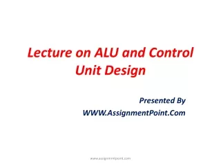
Lecture on ALU and Control Unit Design Presented By WWW.AssignmentPoint.Com www.assignmrntpoint.com
ALU Design Cin • Arithmetic Unit • Logic Unit f3 f2 f1 f0 4-bit parallel adder F A3 A2 A1 A0 x3 x2 x1 x0 X B3 B2 B1 B0 y3 y2 y1 y0 Y Cout Arithmetic Unit www.assignmrntpoint.com
Arithmetic Unit Lets take the following two operations F = X + Y F = X – Y S0 0 1 Cin Y 4-bit parallel adder x3 x2 x1 x0 F Cin 4-bit parallel adder X = X + Y + 0 = X + (-Y) = X + (Y + 1) = X + Y + 1 y3 y2 y1 y0 0 1 0 1 0 1 0 1 f3 f2 f1 f0 MUX MUX MUX MUX F Cout Cout www.assignmrntpoint.com S0
Block Diagram of Arithmetic Unit 4 Arithmetic Unit X 4 F 4 Y S0 www.assignmrntpoint.com
Logic Unit www.assignmrntpoint.com
Block Diagram of Logic Unit 4 Logic Unit X 4 G 4 Y S0 www.assignmrntpoint.com
Block Diagram of ALU 4 Arithmetic Unit X Multiplexer 4 F 4 Y 4 4 Z S0 4 Logic Unit X 4 G 4 Y S0 www.assignmrntpoint.com S1
Design of the Control Unit • Two types of control unit design • Hardwired Control Design • Micro-programmed Control Unit Design www.assignmrntpoint.com
Basic Concepts Transfer to Transfer 14th bit of to 1st bit of Transfer to if E is enabled www.assignmrntpoint.com
Multiplication Using Addition Microprocessor speed depends on bus architecture www.assignmrntpoint.com
Bus Architecture • Three types of bus architectures • Single-bus architecture • Two-bus architecture • Three-bus architecture www.assignmrntpoint.com
Single Bus Architecture www.assignmrntpoint.com
Two-bus Architecture www.assignmrntpoint.com
Timing Signals • One of the main task of control unit is to sequence a set of operations properly • Use a ring counter to implement this www.assignmrntpoint.com
Hardwired Control Design • Eight Steps to follow www.assignmrntpoint.com
Start Step 1: Derive the Flow Chart R 0 M Multiplicand via inbus Q Multiplier via inbus R R + M Q Q – 1 Q=0 no yes Outbus R Stop www.assignmrntpoint.com
Step 2: Obtain register transfer description www.assignmrntpoint.com
Step 3: Specify processing hardware along with various components www.assignmrntpoint.com
Step 4: Complete the design of the processing section 4 4 C0: R ← 0 C1: M ← inbus C2: Q ← inbus C3: F ← r + l C4: Q ← Q – 1 C5: outbus ← R C6: R ← F M R Q L C D C1 C L D L D C C0 C2 C6 C4 4 C3 4-bit adder Z 4 F www.assignmrntpoint.com C5
Step 5: Determine the block diagram of the controller 0 1 2 3 4 5 6 www.assignmrntpoint.com