Download
1 / 20
200 likes | 330 Views
The ILC Beam Delivery System, ATF2 and ESA. Andrei Seryi SLAC DOE High Energy Physics Program Review June 14-15, 2005. The scene. Truly international efforts with more than 100 people are involved in machine and machine-detector aspects of BDS

E N D
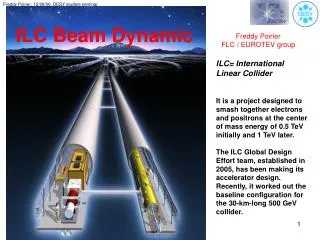
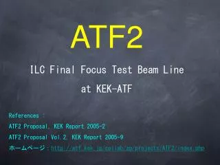
The ILC Beam Delivery System, ATF2 and ESA Andrei Seryi SLAC DOE High Energy Physics Program ReviewJune 14-15, 2005
The scene • Truly international efforts with more than 100 people are involved in machine and machine-detector aspects of BDS • Daresbury, RHUL, QMUL, Oxford, UCL, LAL, CEA/Saclay, CERN, BINP, DESY, INFN, … • KEK, Tokyo University, Kyoto ICR, IHEP, Pohang AL, … • SLAC, BNL, Fermilab, LLNL, Universities, … and many other … • SLAC contribution need to be viewed in this context • Experience of BDS design and operation is one of biggest strength of SLAC • Design and work with SLC Final Focus, instrumentation & MDI aspects • Dedicated international Final Focus Test Beam facility • ILC BDS design – Working Group 4 of ILC • conveners: Grahame Blair, Tomoyuki Sanuki, Andrei Seryi http://www-project.slac.stanford.edu/ilc/acceldev/beamdelivery/
Mature design of BDS; large role of SLAC • Final Focus of SLC design with chromaticity correction by interleaved sextupoles • Non-interleaved (for x and y planes) sextupole pairs – verified at FFTB • The lessons learned at these facilities => FF with local chromaticity correction, designed at SLAC for NLC in 2000, now the basis of ILC BDS • Designs for the IR, BDS instrumentation and beam dumps follow the lessons learned at SLC and are the basis for ILC NLC BDS ~2002
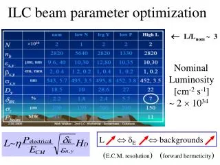
Beam Delivery System challenges • Focus the beam to size of about 500 * 5 nm at IP • Provide acceptable detector backgrounds • collimate beam halo • Monitor the luminosity spectrum and polarization • diagnostics both upstream and downstream of IP is desired • Measure incoming beam properties to allow tuning of the machine • Keep the beams in collision & maintain small beam sizes • fast intra-train and slow inter-train feedback • Protect detector and beamline components against errant beams • Extract disrupted beams and safely transport to beam dumps • Optimize IR for all considered detector concepts • Minimize cost & ensure Conventional Facilities constructability
Choice of crossing angle has crucial influence on the machine performance, reliability, and affect physics reach • NLC @ 3ns bunch spacing => 20mrad x-ing; TESLA @ 300ns => chose head-on • Incoming and outgoing beam are independent (+) • Disrupted beam with large energy spread captured by alternating focusing, no need to bend the beam after collision => easier to minimize beam losses (+) • Require compact SC quads and crab cavity • The exit hole un-instrumented => loss of detector hermeticity (-) • Low energy pairs spread by solenoid field => somewhat larger background (-) • No extra exit hole => somewhat better detector hermeticity (+) • Low energy pairs spread less => somewhat better background (+) • Require electrostatic separator with B-field or RF-kicker • Incoming and outgoing magnets shared => difficult optics, collimation apertures set by outgoing beam (-) • Need to bend disrupted beam with large energy spread => beam loss, especially at high energy, MPS (-)
Evaluation of head-on design by TRC • SLAC actively participated in ILC-TRC in 2002, including • evaluation of BDS design and head-on scheme • Large losses in extraction line, especially at 1 TeV • Incompatible with post-IP E/Polarization diagnostics • Electrostatic separator 100kV/cm at 1TeV – feasibility in high SR environment • MPS issues • g losses at (or near) septum: ~5-15kW • Parasitic collision 26.5 m from IP @ 1TeV • SR masking over-constrained
SLAC contributed to all aspects of turning the Strawman configuration into real design: 1st ILC Workshop November 2004 • Full optics for all beamlines; Well developed and optimized 20mrad optics and magnets design; The method and first iteration of optics and magnets for 2mrad IR; Upstream and downstream diagnostics for both IRs
Optics Based on NLC design • Betatron collimation with survivable spoilers • Energy & polarization diagnostics BDS for 20mrad IR to dump to IR1 11 mrad Big Bend & polarimeter chicane to IR2 ILC2005 Beam Switchyard
20mrad IR, extraction & compact SC quads • IR design based on compact SC quads developed at BNL • Work closely with BNL on design of IR, SC quads, study of its stability • Detailed model in Geant • Close connection with detector groups optimizing IR and detector design
SLAC-BNL-UK-France Task Group 2mrad IR: from concept to optics QF1 • FF and extraction line optimized simultaneously • Quads and sextupoles in the FD optimized to • cancel FF chromaticity • focus the extracted beam O.Napoly, 1997 pocket coil quad
SLAC-BNL-UK-France Task Group 2mrad IP Extraction Line in Geant BYCHIC Shared Large Aperture Magnets Disrupted beam & Sync radiations QEXF1 SF1 QF1 SD0 QD0 60 m Beamstrahlung Incoming beam No beam & g losses for nominal parameters pocket coil quad Super Septum Quad, B.Parker et al.) or Rutherford cable SC quad and sextupole Warm Panofsky septum quad (C.Spencer)
Largest elements of BDS R&D with SLAC involvement • Proposed End Station A at SLAC • Study Interaction Region issues and instrumentation • Mockup of full IR • Existing ATF at KEK (DR and BDS related studies) • Instrumentation (Nano-BPM, laser wires, optical anchor) • Fast Intra-train feedback (FONT/Feather) • nm resolution BPM test & demonstration • Preparation of ‘ATF-2’ • Proposed ATF-2 at KEK • BDS facility, use very low emittance ATF beam
End Station A Test Facility For Prototypes of Beam Delivery and IR Components http://www-project.slac.stanford.edu/ilc/testfac/ESA/esa.html Collimator design, wakefields (T-480) BPM energy spectrometer (T-474) Synch Stripe energy spectrometer (T-475) IP BPMs, kickers EMI (electro-magnetic interference) IR Mockup PAC05 paper/poster: SLAC-PUB-11180 e-Print Archive: physics/0505171
End Station A for recent E158 experiment Experimental hall is 60 meters long E158 completed in Sept. 2003 and all beamline components in ESA have been removed. A concrete bunker (not shown) surrounds the beamline.
ESA Test Facility: First Experiments T-480: Collimator Wakefields Collimators remove beam halo, but excite wakefields. Goal is to determine optimal collimator material and geometry. T-474, T-475: Energy Spectrometers Precision energy measurements to 50-200 parts per million are needed for Higgs boson and top quark mass measurements. BPM and synchrotron stripe spectrometers will both be evaluated in a common 4-magnet chicane.
End Station A Test Facility ILC bunch charge and bunch length E,z bunch distributions in ESA; 2E10 e-/bunch, 28.5 GeV Envision 2-week run in November 2005, and to have 2-week runs ~every 6 months in 2006-2007.
Reasons to develop ATF-2 facility ATF2 collaboration, presently 88 people from 21 labs and institutions and growing KEK, Tsukuba IHEP, Beijing BINP, Novosibirsk CCLRC/DL/ASTeC,Daresbury CEA, Gif-sur-Yvette CERN, Geneva Hiroshima University Kyoto ICR, Kyoto LAL, Orsay LLNL, Livermore NIRS, Chiba-shi North Carolina A&T State University Oxford University Pohang Accelerator Laboratory Queen Mary University of London Royal Holloway, University of London DESY, Hamburg SLAC, Stanford UCL, London University of Oregon University of Tokyo ATF2 proposal is to be released in June, during the BDIR workshop in London • Luminosity issues will be extremely challenging in the LC • Likely more challenging than achieving the beam energy • Complete FFTB studies • FFTB never demonstrated routine operation of FFS • Implement full feedback control and optimization • Operate with ILC like bunch train and IP feedback • Use stable low emittance beam from ATF DR • Learn to operate new FF optics • Experience concurrent with ILC construction • FFTB experience will be over 15 years old • Train new generation of physicists
ATF2 design & goals Optics Design of ATF2 (A) Small beam sizeObtain sy ~ 35nmMaintain for long time (B) Stabilization of beam center Down to < 2nm by nano-BPM Bunch-to-bunch feedback of ILC-like train Beam New diagnostics existing extraction New final focus New Beamline
Advanced beam instrumentation at ATF2 • BSM to confirm 35nm beam size • nano-BPM at IP to see the nm stability • Laser-wire to tune the beam • Cavity BPMs to measure the orbit • Movers, active stabilization, alignment system • Intratrain feedback, Kickers to produce ILC-like train IP Beam-size monitor (BSM) (Tokyo U./KEK, SLAC, UK) Laser-wire beam-size Monitor (UK group) Laser wire at ATF Cavity BPMs, for use with Q magnets with 100nm resolution (PAL, SLAC, KEK) Cavity BPMs with 2nm resolution, for use at the IP (KEK)
Summary • ILC BDS design is making progress from the concept to optics, from optics to engineering design • Strong R&D program is planned and ongoing • SLAC actively contributing to all aspects of BDS design and R&D