Download
1 / 105
1.08k likes | 1.32k Views
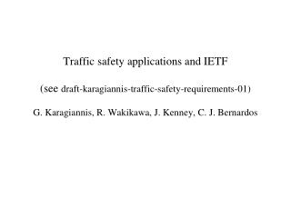
FPGA: Applications and Examples. Wu, Jinyuan Fermilab June 2014. Introduction. A design example of a TDC is presented in detail. T he functional blocks used in this TDC is expected reusable in other projects. Design Example: ADC without ADC. Digitization of Analog Waveforms.

E N D
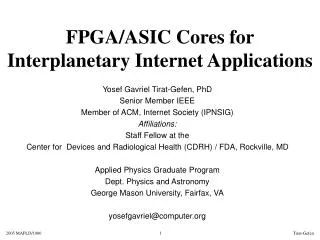
FPGA: Applications and Examples Wu, Jinyuan Fermilab June 2014
Introduction • A design example of a TDC is presented in detail. • The functional blocks used in this TDC is expected reusable in other projects. FPGA: Applications and Examples
Design Example:ADC without ADC FPGA: Applications and Examples
Digitization of Analog Waveforms Slow Digitization ~50 MSPS Fast Digitization ~5 GSPS via DRS4 slow down to ~50 MSPS FPGA FPGA DRS4 ADC AMP & Shaper ADC ADC AMP & Shaper ADC ADC AMP & Shaper ADC ADC AMP & Shaper ADC • There are applications of digitizing slow waveforms at 20 to 50 MSPS. • Fast waveforms can be stored in DRS4 and digitized at slower rate. • ADC chips cost and power consumption are relatively high. FPGA: Applications and Examples
V1 V1 V3 V3 V2 V2 V4 V4 T1 T1 T2 T2 T3 T3 T4 T4 FPGA ADC Using FPGA AMP & Shaper ADC AMP & Shaper ADC • Analog signals from AMP & Shapers are directly fed to FPGA pins. • FPGA outputs and passive RC network are used to generate ramping reference voltage VREF. • The input voltages and VREF are compared using FPGA differential input receivers. • The times of transitions representing input voltage values are digitized by TDC blocks in FPGA. AMP & Shaper ADC AMP & Shaper ADC FPGA AMP & Shaper TDC AMP & Shaper TDC AMP & Shaper TDC AMP & Shaper TDC VREF R1 R1 C FPGA: Applications and Examples R2
Using TDC as ADC: Single Ended Version FPGA TDC TDC VREF 50 50 Input Waveform, Overlap Trigger & Reference Voltage 1000pF 100 Raw Data Converted FPGA: Applications and Examples
Using TDC as ADC: Differential Version 4xR2 FPGA VIN1+ TDC VIN1- VIN2+ TDC VIN2- 4xR2 R R C VREF+ R1 VREF- FPGA: Applications and Examples
TDC Core: High Hit Rate High Precision Version • Input transitions are sampled in the delay line & sampling register array. The position of the transition in the array reflect transition time. • The position is encoded into fine time. • The raw time data are send through the bin-by-bin calibration block to compensate for the differences of the bin widths. • The encoded times of transitions are temporarily stored in the pipeline buffer. • When the device is triggered, data in the pipeline buffers are read out via the data load transfer registers. • The coarse times are attached with the fine times and stored in the zero suppression buffer. • Data are sent out of the device using LVDS serial link. Pipeline Buffer Encoder & Calibration IN3 Pipeline Buffer Encoder & Calibration IN2 Encoder & Calibration Pipeline Buffer IN1 Encoder & Calibration Pipeline Buffer Data Load/ Transfer Register Delay Line & Sampling Register Array IN0 Trigger Logic & Timing Event Buffer w/ Zero Suppression CK250 Serialize Data Output Channel, Coarse Time Reset Trigger FPGA: Applications and Examples
Pipeline Buffer Encoder & Calibration IN3 Pipeline Buffer Encoder & Calibration IN2 Encoder & Calibration Pipeline Buffer IN1 Encoder & Calibration Pipeline Buffer Data Load/ Transfer Register Delay Line & Sampling Register Array IN0 Delay Line &Sampling Register Array Trigger Logic & Timing Event Buffer w/ Zero Suppression CK250 Serial Data Output Channel, Coarse Time Reset Trigger FPGA: Applications and Examples
TDC Using FPGA Logic Chain Delay • This scheme uses current FPGA technology • Low cost chip family can be used. (e.g. EP2C8T144C6 $31.68) • Fine TDC precision can be implemented in slow devices (e.g., 20 ps in a 400 MHz chip). IN CLK FPGA: Applications and Examples
Good, However • Auto calibration solved some problems • However, it won’t eliminate the ultra-wide bins FPGA: Applications and Examples
Wave Union TDC records multiple transitions. Wave Union Launcher A Regular TDC records only one transition Wave Union Launcher A 0: Hold 1: Unleash In CLK FPGA: Applications and Examples
Wave Union Launcher A: 2 Measurements/hit 1: Unleash FPGA: Applications and Examples
1 2 Sub-dividing Ultra-wide Bins 1: Unleash Device: EP2C8T144C6 • Plain TDC: • Max. bin width: 160 ps. • Average bin width: 60 ps. • Wave Union TDC A: • Max. bin width: 65 ps. • Average bin width: 30 ps. 1 2 FPGA: Applications and Examples
Pipeline Buffer Encoder & Calibration IN3 Pipeline Buffer Encoder & Calibration IN2 Encoder & Calibration Pipeline Buffer IN1 Encoder & Calibration Pipeline Buffer Data Load/ Transfer Register Delay Line & Sampling Register Array IN0 Encoder & Calibration Trigger Logic & Timing Event Buffer w/ Zero Suppression CK250 Serial Data Output Channel, Coarse Time Reset Trigger FPGA: Applications and Examples
Encoder of Thermometer Code D QY • When the sampling register array outputs a thermometer code, a transition is captured by the TDC. • The transition is detected by a set of AND gates. • For an ideal thermometer code, only one output of the AND gates =1. • Several OR gates are used to generate the fine time value (QTF[5..0]) and the fine time valid signal (QTFV). • Note that in practical design, two stages of pipeline registers are inserted to ensure fast operating frequency. • Every clock cycle, there is a QTF value output. But it is a valid hit only if QTFV = 1. QY[31] 31 QTFV QY[0] QY[31] QY[n] = D[n] & !D[n+1] QTF[5] QY[16] QTF[4] QTF[3] QTF[2] QTF[1] QY[31] QTF[0] QY[3] QY[1] 0 FPGA: Applications and Examples
Bubbles in Thermometer Code D QY 31 QY[n] = D[n] & !D[n+1] QY[n] = D[n] & !D[n+1] & !D[n+2] & … • In practical implementation, the output of the sampling register arraymay have a “bubble” in the thermometer code. • Regular transition detecting logic would set multiple bits. • An modified logic will eliminate the bubble and output only the first edge. 0 FPGA: Applications and Examples
Taking Bubbles into Account t0 + dt1 + dt2 + dt3 +dt4 t0 + dt1 + dt2 + dt3 t0 + dt1 t0 + dt1 + dt2 t0 • The bubbles are correlated to the input time. • The number of set bits is a better code for input time. n n+4 n+3 n+1 n+2 FPGA: Applications and Examples
Encoder of Wave Union TDC D QY 31 QY[n] = QTFV • In the wave union TDC, the output from the sampling register array contains multiple transitions. • The locations of each transitions are encoded and these location codes are combined into one fine time code. • One combination method we used is to sum the first and the third location codes. QTF[] 0 FPGA: Applications and Examples
Auto Calibration Using Histogram Method • It provides a bin-by-bin calibration at certain temperature. • It is a turn-key solution (bin in, ps out) • It is semi-continuous (auto update LUT every 16K events) 16K Events DNL Histogram S LUT In (bin) Out (ps) FPGA: Applications and Examples
Histogram Booking TF RA,WA +1 FPGA: Applications and Examples
D Q D Q D Q D Q D Q RAM D WA WE RA Q Block RAM Based Histogram TF4 TF3 TF2 TF1 TF0 TFV • Pipelined structure allows higher operating frequency yielding higher throughput. • Restriction: Same bin is not hit within 4 cycles. +1 N1 N0+1 FPGA: Applications and Examples
Calibration Pulse Generation: Random != Uniform 16384 Events • When number of events is finite, random hits has large fluctuations. • Pulses with evenly spread timing relative to the TDC clock are desirable. FPGA: Applications and Examples
Cascaded PLL Circuits CK250a CLOCK_50 CK251c • Two stages of PLL circuits are cascaded together. • f(CK250a) = 250 MHz • f(CK251c) = 250.06 MHz • f(CK251c) = (4096/4095)*f(CK250a) • T(CK250a) - T(CK251c) = 0.97 ps. FPGA: Applications and Examples
Test Result in an Oscilloscope Screen Capture Calibration Lookup Table Trigger Edges By CK250a Calibration Edges By CK251c • A total of 16384 Calibration edges are collected. • Entire 4000 ps range are scanned 4 times (4*4096 = 16384). • The histogram (with 50 ps/bin) serves as a demonstration of calibration lookup table. FPGA: Applications and Examples
Pipeline Buffer Encoder & Calibration IN3 Pipeline Buffer Encoder & Calibration IN2 Encoder & Calibration Pipeline Buffer IN1 Encoder & Calibration Pipeline Buffer Data Load/ Transfer Register Delay Line & Sampling Register Array IN0 Pipeline Buffer Trigger Logic & Timing Event Buffer w/ Zero Suppression CK250 Serial Data Output Channel, Coarse Time Reset Trigger FPGA: Applications and Examples
RAM D WA WE RA Q Pipeline & Its Implementation • A pipeline stores one data word per clock cycle, regardless the data is valid or not. • The pipeline looks like register arrays chained together. • But it is more economical to implement using block RAM inside FPGA. D Q D Q D Q D Q D Q WE=1 (RESET) CNT FPGA: Applications and Examples
RAM D WA WE RA Q Pipeline Buffer with Ping-Pong Pages PGW, Writing Page PGR = !PGW, Reading Page WA, Writing Address RA, Reading Address • A single RAM block (e. g. 256 words) is divided into two logic pages with 128 words each. • Selection of the two pages is done by the highest address bit. • TDC data are stored in the writing page. • After 128 clock cycles, new data overwrite the old data. The page keeps a history of 128 clock cycles long. • Once a trigger arrives, the writing and reading pages swap to each other, the data before trigger will be read out while the new data are stored into the current writing page. PGW PGR WA6 =TC6 RA6 5 5 4 4 WE=1 3 3 2 2 1 1 WA0 =TC0 0 FPGA: Applications and Examples
Pipeline Buffer Encoder & Calibration IN3 Pipeline Buffer Encoder & Calibration IN2 Encoder & Calibration Pipeline Buffer IN1 Encoder & Calibration Pipeline Buffer Data Load/ Transfer Register Delay Line & Sampling Register Array IN0 Data Load andTransfer Register Trigger Logic & Timing Event Buffer w/ Zero Suppression CK250 Serial Data Output Channel, Coarse Time Reset Trigger FPGA: Applications and Examples
The Load/Transfer (Shift) Registers D3[] Q[] D2[] Q[] • When LD=1, data from D3[] to D0[] are load to the register array. • When LD=0, data are shifted out of the Q0[] port, one word per clock cycle. • Data from multiple channels are merged into a single stream. D1[] Q[] D0[] Q[] Q0[]=D0,D1,D2,D3 LD =1,0,0,0 FPGA: Applications and Examples
Pipeline Buffer Encoder & Calibration IN3 Pipeline Buffer Encoder & Calibration IN2 Encoder & Calibration Pipeline Buffer IN1 Encoder & Calibration Pipeline Buffer Data Load/ Transfer Register Delay Line & Sampling Register Array IN0 Trigger Logic &Timing Trigger Logic & Timing Event Buffer w/ Zero Suppression CK250 Serial Data Output Channel, Coarse Time Reset Trigger FPGA: Applications and Examples
Trigger and Timing • Upon Reset, the coarse time counter counts from 0. • When trigger arrives, a internal readout sequence is started which controls data moving out of pipeline to the event buffer. Input Signal Conditioning (Optional) RSTP Coarse Time Counter TC (WA) Reset MC (RA) TRIGP Readout Sequencer Input Signal Conditioning (Optional) LD Trigger ECNT Trigger Logic & Timing Reset Trigger FPGA: Applications and Examples
Signal Conditioning: De-Glitch • For most signals received from outside of the FPGA device, receiving it with a D flip-flop is usually sufficient. • If the external signal travels over very long cable and the termination is poor, the de-glitch circuit shown above can be used. • More delay stages can be added for even better performance. FPGA: Applications and Examples
Signal Conditioning: De-Bounce • If the input is a mechanical switch, de-bouncing is usually necessary. • The active input causes a counter to set with MSB (Qcnt[7]) becomes 1. • When the input = 0, the MSB is still high and the counter increases by 1 every clock cycle. • After 128 clock cycles, the MSB becomes 0. • This way, the output signal OUTP is a smooth pulse without glitch as long as the off time interval of the SW is < 128 clock cycles. FPGA: Applications and Examples
A Counter with Synchronous Load as a Sequencer 0: Disable +1: Inc D[] SLOAD 0/+1 A+B D[] Q[] SLOAD B[] D[] Q[] CNTEN • A loadable counter can be used as a simple sequencer. • Q[7] is used as counter enable CNTEN. • Once 128+M is loaded, the counter counts 128-M clock cycles. FPGA: Applications and Examples
Signal Conditioning: Multi- to Single-Cycle Pulse • This circuit samples 0 to 1 transitions. • The input pulse width can be 1 or more clock cycles. • For each input transitions, a single cycle pulse is generated. FPGA: Applications and Examples
RAM D WA WE RA Q Coarse Time & Pipeline Writing PGW, Writing Page RSTP Coarse Time Counter TC (WA) • After reset, the coarse time counter TC counts from 0. • TC can be as many bit as required, e.g. 32 bits is sufficient to represent 4G clock cycles, or 16 s if clock frequency is 250 MHz. • The lower 7 bits TC[6..0] are used as WA[6..0]. • The writing page is filled repeatedly every 128 cycles. WA, Writing Address PGW WA6 =TC6 WE=1 5 4 3 2 1 WA0 =TC0 FPGA: Applications and Examples
RAM D WA WE RA Q Event Window m=(M mod128) M=n-L1 Reading Page (Was WP) WA=(TC mod 128) L1 TC=n L2 RA, Reading Address PGR MC (RA) • When a TRIGP pulse arrives, the writing page becomes the reading page. • A timing window starting from L1 cycles before the current TC and L2 cycles wide are to be read out. • The trigger timing block will set RA to M and then increase RA from m to (m+L2 mod 128). • In the trigger logic, two loadable counters are implemented: • ECNT, 10 bits, used to enable both counters to read out L2 memory locations for 4 channels. • MC, 34 bits, used to indicate coarse time and generate RA. • A load pulse is also generated for the Data Load/Transfer Registers. TRIGP Readout Sequencer RA6 LD PGR(!PGW) 5 ECNT 4 3 2 1 0 FPGA: Applications and Examples
Readout Timing • After trigger, PGW and PGR swaps. Writing page becomes reading page. • The ECNT generate a count enable signal CNTEN a total of 4*L2 cycles long (L2=[1, 128]). • RA starts from location m and increase every 4 clock cycles allowing 4 channels to output. • LD becomes high every 4 clock cycles to load data to the transfer register. FPGA: Applications and Examples
Pipeline Buffer Encoder & Calibration IN3 Pipeline Buffer Encoder & Calibration IN2 Encoder & Calibration Pipeline Buffer IN1 Encoder & Calibration Pipeline Buffer Data Load/ Transfer Register Delay Line & Sampling Register Array IN0 Event Buffer &Zero Suppression Trigger Logic & Timing Event Buffer w/ Zero Suppression CK250 Serial Data Output Channel, Coarse Time Reset Trigger FPGA: Applications and Examples
Zero-Suppression Scheme • A TDC data word is written into a FIFO buffer only when the hit is valid, i.e., TFV = 1. • When the data is zero suppressed, coarse time information is not correlated with the memory address. Therefore, the coarse time must be added to the data. • For multi-channel data concentration, channel id must be added as well. • A header may also be written into the FIFO to create a block of data. TC TC Header FIFO TDC TF OUT TFV PUSH Write Header FPGA: Applications and Examples
Data Concentration Path D LD • When TRIGP pulse arrives, a header is written into the FIFO and the MC signal starts counting. • The RA and LD are derived from MC and data in pipeline buffers are concentrated into one stream containing fine time, TF and data valid signal TFV. • The delayed version of MC represents channel ID CH and the coarse time TCR of the data in the output stream. • If the hit is valid, a data word including TCR, TF and CH is pushed into the FIFO. Pipe Line Buffer Pipe Line Buffer Pipe Line Buffer Pipe Line Buffer D WA WE RA D WA WE RA D WA WE RA D WA WE RA Q Q Q Q D LD D LD RA D LD TFV,TF Header FIFO TCR,TF,CH OUT LD TFV TRIGP PUSH CNT MC D Q D Q D Q TCR,CH TRIGP = Write Header FPGA: Applications and Examples
Data Concentration Timing • This diagram explains the details of the data concentration timing. • Note that RA, LD, CH and TRC signals are derived from MC. FPGA: Applications and Examples
FIFO Almost Full Logic Header FIFO TCR,TF,CH OUT TFV PUSH Almost Full TRIGP = Write Header • If the trigger system is well designed, the FIFO is less likely to become full, but guarding logic must be designed to ensure reliability of the data. • One possibility is to bring the Almost Full bit of the FIFO to the data to alert a possible data loss. FPGA: Applications and Examples
Pipeline Buffer Encoder & Calibration IN3 Pipeline Buffer Encoder & Calibration IN2 Encoder & Calibration Pipeline Buffer IN1 Encoder & Calibration Pipeline Buffer Data Load/ Transfer Register Delay Line & Sampling Register Array IN0 SerialData Output Trigger Logic & Timing Event Buffer w/ Zero Suppression CK250 Serial Data Output Channel, Coarse Time Reset Trigger FPGA: Applications and Examples
Serial Data Output Shift Register Load • Use a shift register for parallel to serial conversion. • If the data link is DC coupled, a plain serial data should be good. • If the data link is AC coupled, consider a AC balanced coding scheme such as 8B/10B FPGA: Applications and Examples
Plain Serial Data ENGLISH “Hello world.” H e l l o (Space) w o r … FRENCH “Bonjour tout le monde.” B o n j o u r (Space) t … • Two streams of the plain serial data • The starting is indicated by the first 1->0 transition after long continuous 1’s. FPGA: Applications and Examples
Serial Data with 8B/10B Encoding K28.1 31 Bytes ID Header 32 Bytes (8 32-bit Words) Register Data 64 Bytes (16 32-bit Words) Scalar Counts K28.1 8064 Bytes (2016 32-bits Words) TDC Hit Data • A byte of 8-bit payload is transmitted with 10 bits. • A special code K28.1 that has 0111110 or 1000001 pattern is used to indicate the boundary of the data frame. (See example) Padding 0’s FPGA: Applications and Examples
Outputting Plain Code & 8B/10B Code Shift Register Shift Register 8B/10B Encoder FIFO FIFO Pop Pop Load Load 32 Clock Cycles 40 Clock Cycles • In our design, assume width of the data words in FIFO is 32 bits. • The Pop and the Load signals pulse up every 32 clock cycles for outputting plain code. • To output 8B10B code, a 8B/10B encoder is inserted. The pulse period of Pop and Load signals is 40 cycles. FPGA: Applications and Examples
TDC Core: High Hit Rate High Precision Version Pipeline Buffer Encoder & Calibration IN3 Pipeline Buffer Encoder & Calibration IN2 Encoder & Calibration Pipeline Buffer IN1 Encoder & Calibration Pipeline Buffer Data Load/ Transfer Register Delay Line & Sampling Register Array IN0 Trigger Logic & Timing Event Buffer w/ Zero Suppression CK250 Serialize Data Output Channel, Coarse Time Reset Trigger FPGA: Applications and Examples