Download
1 / 7
70 likes | 202 Views
DSC for T0. T0 Collaboration presented by W.H.Trzaska and V.Grigoriev. Very preliminary!. T0 – what it is:. Two arrays of 12 PMT T0 Right (0.7 m) T0 Left ( - 3.5 m) Two shoe boxes of fast electronics inside the magnet Few creates of electronics outside the magnet Laser calibration system.

E N D
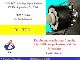
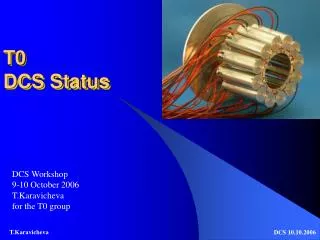
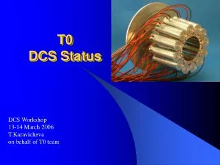
DSC for T0 T0 Collaborationpresented byW.H.Trzaska and V.Grigoriev Very preliminary!
T0 – what it is: • Two arrays of 12 PMT • T0 Right (0.7 m) • T0 Left ( - 3.5 m) • Two shoe boxes of fast electronics inside the magnet • Few creates of electronics outside the magnet • Laser calibration system ALICE Week March 2003
General readoutscheme for T0: ALICE Week March 2003
Layout and connections: ALICE Week March 2003
Cables and connection from L3 • HV cables • 2 x 12 • Coaxial cables • Thresholds 2 x 12 • Bunch crossing 2 x 1 • Time individual 2 x 12 • Output Amplitudes 2 x 12 • TRD wake up 2 x 4 • T0 right/left 2 x 1 • Optical fibre • 2 x 12 ALICE Week March 2003
What has to be controlled: • 24 HV channels • Can use spare channels from V0 • Low voltage for the shoe boxes • Not yet selected as the design of the electronics is not completed • Should be able to use standard solutions • Expected requirements for one shoe box – 28 W: • +12 V 576 mA 6912 mW • +6 V 720 mA 4320 mW • -6 V 2760 mA 16560 mW • 24 thresholds of CFDs and 24 delays • Laser and electronics outside L3 ALICE Week March 2003
Functional diagram of the laser calibration: ALICE Week March 2003