Download
1 / 31
380 likes | 521 Views
Learn about the origin of soils, three-phase diagram, important terms, Atterberg's limits, and various types of soils formed by different processes. Understand soil properties, relationships, and calculations in soil mechanics.

E N D
CE6405 SOIL MECHANICS Prepared by,Mrs. M. RAMALAKSHMI,AP-CIVIL,MSEC – KILAKARAI.
LectureOutline Topics fordiscussion Origin ofSoils Three PhaseDiagram ImportantTerms PhaseRelationships Atterberg’slimits
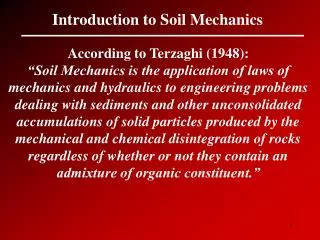
Soils are formed by weathering of rocks due tomechanical • disintegration or chemicaldecomposition. • Exposed rocks are eroded and degraded by variousphysical and chemicalprocesses. • The products of erosion are picked up and transportedto some other place by wind wateretc. • This shifting of material disturbs the equilibrium offorces on the earth and causes large scale movements and upheavals. Origin ofSoils
Types ofSoils Glacial soils:formedbytransportationanddeposition of glaciers. Alluvial soils: transported by running water and deposited along streams. Lacustrine soils: formed by deposition in quiet lakes (e.g. soils in Taipeibasin). Marine soils: formed by deposition in the seas (HongKong). Aeolian soils: transported and deposited by the wind (e.g. soils in the loess plateau,China). Colluvial soils: formed by movement of soil from its original place by gravity, such as during landslide (Hong Kong). (from Das,1998)
Soilparticle Water(electrolytes) Air Three Phases inSoils
PHASEDIAGRAM For purpose of study and analysis, it is convenient to represent the soil by a PHASE DIAGRAM, with part of the diagram representing the solid particles, part representing water or liquid, and another part air or othergas.
VolumetricRatios Void ratioe e Volumeof voids Vv VolumeofsolidsVs Porosity n% Vv Volumeofvoids n 100 Totalvolumeof soilsample Vt Saturated (3) Degree of SaturationDSr%y (0 –100%) S Totalvolumeof voidscontainswater Vw Totalvolumeof voids Vv 100%
WeightRatios (1) Water Contentw% Weight ofwater w Ww 100% Weightof soilsolids Ws
(1) Dry unitweight Soil unitweights Weightof soilsolids Ws d TotalvolumeofsoilV t (2) Total, Wet, Bulk, or Moist unitweight Totalweight of soil (4) Submerged unitweight ' sat w Ws Ww Totalvolumeof soil Vt (3) Saturated unit weight (considering S=100%, Va=0) Weightof soil solids water Ws Ww sat TotalvolumeofsoilV t Note: The density/or unit weight are ratios which connects the volumetric side of the PHASE DIAGRAM with the mass/or weightside.
Specific gravity,Gs The ratio of the weightofsolid particles to the weight of an equal volume of distilled water at4°C ws G s Vs w i.e., the specific gravity of a certain material is ratio of theunit weight of that material to theunit weightof water at 4oC. The specific gravity of soil solids is often needed for various calculations in soilmechanics. • Gw =1 • Gmercury =13.6 G s s w
Relationships Between Various PhysicalProperties All the weight- volume relationships needed in soil mechanics can be derived from appropriate combinations of six fundamental definitions. Theyare: Voidratio Porosity Degree ofsaturation Watercontent Unit weight Specificgravity
1. Relationship between e andn Using phasediagram Given :e required: n e 1+e e nVv 1 Vt 1e
2. Relationship among e, S, w, andGs w ww wVwwVwVw ws sVs wGsVs GsVs • Dividing the denominator and numerator of theR.H.S. by Vv yields: Se wGs • This is a very useful relation for solving THREE-PHASE • RELATIONSHIPS.
3. Relationship among , e, S andGs W WwWs wVw sVs wVwwGsVs V Vs Vv Vs Vv Vs Vv (Se Gs ) w 1e • Notes: • Unit weights for dry, fully saturated and submerged casescanbe derived from the upperequation • Water content can be used instead of degree of saturation.
Method : Memorizerelationships Method to solve PhaseProblems (SeGs) Se wGs w 1e e n d 1w 1e
Example2 Field density testing (e.g., sand replacement method) has shown bulk density of a compacted road base to be 2.06 g/cc with a water content of 11.6%. Specific gravity of the soil grains is 2.69. Calculate the dry density, porosity, void ratio and degree ofsaturation.
RelativeDensity • The relative density is the parameter that compare thevolume • reductionachievedfromcompactiontothemaximumpossible • volumereduction • The relative density Dr, also called density index is commonly used to indicate the IN SITU denseness or looseness of granularsoil. Volume reduction from compaction of granularsoil
Dr can be expressed either in terms of voidratios • or dry densities. 23
Remarks • The range of values of Dr may vary from a minimum of zero for very LOOSE soil to a maximum of 100% for a very DENSEsoil. • Because of the irregular size and shape of granular particles, it is not possible to obtain a ZERO volume ofvoids.
Granular soils arequalitativelydescribed according to their relative densities as shownbelow • The use of relative density has been restricted to granular soils because of the difficulty of determining emax in clayey soils. Liquidity Index in fine-grained soils is of similar use as Dr in granular soils.
Liquid limit test: • A soil is place in the grooving tool which consistsof brass cup and a hard rubberbase. • A groove is cut at the center of the soil pat usinga standard groovingtool. • The cup is then repeatedly drooped from a heightof 10mm until a groove closure of 12.7mm. • The soil is then removed and its moisture content is determined. • The soil is said to be at its liquid limit when exactly 25drops are required to close the groove for a distance of 12.7 mm (one half of aninch) ATTERBERGLIMITS
Plastic limittest: • A soil sample is rolled into threads until it becomes thinnerand eventually breaks at 3mm. • it is defined as the moisture content in percent at which thesoil crumbles when rolled into the threads of 3.0mm. • If it is wet, it breaks at a smaller diameter; if it is dry it breaks ata largerdiameter.
REFERENCES: • GOOGLE.COM • WWW.SLIDESHARE.COM • SOIL MECHANICS ANDFOUNDATION ENGINEERING BYK.R.ARORA