Download
1 / 17
170 likes | 173 Views
Tracking in High Density Environment. Jouri BELIKOV (CERN) Peter HRISTOV (CERN) Marian IVANOV (CERN) Karel SAFARIK (CERN). Outlook. The ALICE detector description ALICE Transition Radiation Detector (TRD) Working principle Local reconstruction TRD tracking algorithm Results. HMPID

E N D
Tracking in High Density Environment JouriBELIKOV (CERN)PeterHRISTOV (CERN)MarianIVANOV (CERN)KarelSAFARIK (CERN)
Outlook • The ALICE detector description • ALICE Transition Radiation Detector (TRD) • Working principle • Local reconstruction • TRD tracking algorithm • Results
HMPID PID (RICH) @ high pt PMD g multiplicity TPC Tracking, dEdx MUON m-pairs The ALICE Experiment TOF PID TRD Electron ID, Tracking PHOS g,p0 ITS Low pt tracking Vertexing
The TRD Characteristics • 18 super modules • 6 radial layers • 5 longitudinal stacks • 540 chambers • 750m2 active area • 28m3 of gas Each chamber: ≈ 1.45 x 1.20m2 ≈ 12cm thick (incl. Radiators and electronics) in total1.18 million read out channels
Working Principle of the TRD • Drift chambers with FADC readout at 10MHz combined with a fiber/ foam sandwich radiator in front. • Transition Radiation (TR) photons (< 30keV, only for electrons) are absorbed by high-Z gas mixture (Xe,Co2) large clusters
Local Reconstruction • For each time bin (X direction) the position of the cluster along the pad rows (Y direction) is reconstructed: • Lookup table (amplitudes of the maximum and the two neighbors) used instead of COG to minimize non-linearity's • Fast calculation, better precision than a Mathieson fit. • The track parameters are obtained from a straight line fit.
Precision of Local Reconstruction Resolution Cluster RMS • Y-Position resolution is determined by the S/N ratio and by the incident angle • Resolution is not proportional to the cluster’s RMS • Better estimate of uncertainty during tracking – knowing incident angle • Uncertainty in x-coordinate (time) • Width of time response function (local – on cluster level) • Unisochronity effect and non-homogeneity of drift velocity (global shift of tracklet) • Signal shaping (software tail cancellation) before local reconstruction • Reduction of the uncertainty in x • Local Signal processing Unisochronity
TOF TRD TPC ITS Combined Tracking • Combining tracking - Iterative process • Forward propagation towards to the vertex –TPC-ITS • Back propagation –ITS-TPC-TRD-TOF • Refit inward TOF-TRD-TPC-ITS • Continuous seeding and track segment finding in all detectors • TRD tracking • Back propagation to TOF – all clusters are considered • Refit inward • Starts from the last chamber before crossing the frame or from the last “gold tracklet”
TRD Tracking: Challenge • High density environment ~ about 1.5 clusters in track road • Significant material budget in the TRD volume • Fraction of tracks is absorbed ~ 35% • Mean energy losses ~15 % of energy Material budget Absorption points Fraction of non absorbed tracks
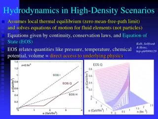
Energy Losses in the TRD • Left side – relative energy loss in TRD detector • Integrated over all tracks reached TOF - Hijing events • Right side – precision of dEdx correction
Energy Losses: Correction • TGeoManager used to get information necessary for energy loss calculation and multiple scattering • Local information: density, radiation length, Z, A defined in each point • Mean query time ~ 15 ms • Mean number of queries • ~15 – between 2 ITS layer • ~15 – between 2 TRD layers • Two options considered • 1. Propagate track up to material boundary defined by modeler – get local material parameters • Time consuming - too many propagations and updates of the track • 2. Calculate mean parameters between start and end point • <density>, <density*Z/A>, <radiation length> • Faster (only one propagation), reusable in case of parallel hypothesis
TRD Tracking • TRD tracking in high density environment • Non combinatorial Kalman filter (tracks from TPC): 120 propagation layers in 6 planes • Riemann sphere fit for TRD standalone tracking and seeding • Cluster association replaced with tracklet search in each plane • High flux ~ 1.5 clusters in the road defined by cluster and track positions uncertainty • Chi2 minimization for full tracklet not for separate clusters • Several hypothesis investigated Tracklet: set of clusters belonging to the same track in one chamber
Tracklet Search: Principles • R-phi resolution on the level of 0.04 cm • Track extrapolation has ~ 2 times worse resolution than the tracklet resolution • Z - rectangular distribution given by length of pads (+-5 cm) • Probability to cross the pad-row on the level of 15 % - (3.6cm*tan(q)/10cm) • Track can cross the pad-row once at maximum Clusters in road - R – phi projection Clusters in road - Z projection
Tracklet Search • Combinatorial algorithm too expensive • Case of 2 tracks in road – 1 million combinations • Reduction – restricting number of row-crossing points (1 maximum) • Iterative algorithm: • 1 approximation - closest clusters to the track taken • Resolve trivial z swapped clusters • { • Tracklet position, angle and their uncertainty calculated • Weighted mean position calculated (tracklet+ track) • Chi2 calculation for tracklet • Closest clusters to the weighted mean taken • } • Projection algorithm • Loop over possible change of z direction • { • Calculates residuals • Find sub-sample (number of time bins in plane) of clusters with minimal chi^2 distance to the weighted mean (track + tracklet) • Simple sort used – N problem • } Projection
Clusters: Error Parameterizationwithin the Tracklet • Fluctuation of cluster’s position • Estimated as RMS of tracklet - cluster residuals • N - number of clusters in the tracklet • dy – cluster residual from a straight line fit • Uncertainty corresponding to collective shifts of tracklet added to all clusters • Correction for unisochronity and width of the Time Response Function • Systematic shift – multiplication factor N • Additional penalty factor for mean number of clusters per layer and number of pad-rows changes
Performance: Transverse Momentum Resolution • Low density environment • ITS +TPC – without TRD detector • Old TRD tracking – error parameterization based only on cluster shape • New TRD tracking – cluster error parameterization with angular dependence (without unisochronity correction) • New TRD tracking (cor) – chamber calibrated (with unisochronitiy correction) • High density environment (dNch/dy~5000) • ITS +TPC – without TRD detector • New TRD tracking with unisochronity correction
Conclusion • TRD detector was originally developed for electron identification • It is also very useful for reconstruction: • Excellent space resolution for high momentum track (small incident angle) significant improvement in the momentum resolution • Works in high density environment • The most significant improvement is due to the correct error parameterization