Download

1 / 31
320 likes | 974 Views
Learn about interrupts, classification, vectors, responding to interrupts, 8085 interrupt inputs, vector table, RST instructions, interrupt process, and more for better comprehension.

E N D
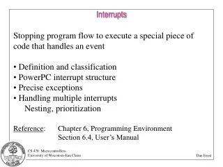
Interrupts • Interrupt is a process where an external device can get the attention of the microprocessor. • The process starts from the I/O device • The process is asynchronous. • Classification of Interrupts • Interrupts can be classified into two types: • Maskable Interrupts(Can be delayed or Rejected) • Non-Maskable Interrupts (Can not be delayed or Rejected) • Interrupts can also be classified into: • Vectored (the address of the service routine is hard-wired) • Non-vectored (the address of the service routine needs to be supplied externally by the device)
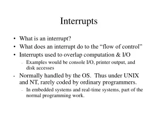
Interrupts • An interrupt is considered to be an emergency signal that may be serviced. • The Microprocessor may respond to it as soon as possible. • What happens when MP is interrupted ? • When the Microprocessor receives an interrupt signal, it suspends the currently executing program and jumps to an Interrupt Service Routine (ISR) to respond to the incoming interrupt. • Each interrupt will most probably have its own ISR.
Responding to Interrupts • Responding to an interrupt may be immediate or delayed depending on whether the interrupt is maskable or non-maskable and whether interrupts are being masked or not. • There are two ways of redirecting the execution to the ISR (Interrupt Service Routine) depending on whether the interrupt is vectored or non-vectored. • Vectored: The address of the subroutine is already known to the Microprocessor • Non Vectored: The device will have to supply the address of the subroutine to the Microprocessor
The 8085 Interrupts • When a device interrupts, it actually wants the MP to give a service which is equivalent to asking the MP to call a subroutine. This subroutine is called ISR (Interrupt Service Routine) • The ‘EI’ instruction is a one byte instruction and is used to Enable the non-maskable interrupts. • The ‘DI’ instruction is a one byte instruction and is used to Disable the non-maskable interrupts. • The 8085 has a single Non-Maskable interrupt. • The non-maskable interrupt is notaffected by the value of the Interrupt Enable flip flop.
The 8085 Interrupts • The 8085 has 5 interrupt inputs. • The INTR input. • The INTR input is the only non-vectored interrupt. • INTR is maskable using the EI/DI instruction pair. • RST 5.5, RST 6.5, RST 7.5 are all automatically vectored. • RST 5.5, RST 6.5, and RST 7.5 are all maskable. • TRAP is the only non-maskable interrupt in the 8085 • TRAP is also automatically vectored
8085 Interrupts TRAP RST7.5 RST6.5 RST 5.5 INTR INTA 8085
Interrupt Vectors and the Vector Table • An interrupt vector is a pointer to where the ISR is stored in memory. • All interrupts (vectored or otherwise) are mapped onto a memory area called the Interrupt Vector Table (IVT). • The IVT is usually located in memory page 00 (0000H - 00FFH). • The purpose of the IVT is to hold the vectors that redirect the microprocessor to the right place when an interrupt arrives.
The 8085 Non-Vectored Interrupt Process • The interrupt process should be enabledusing the EI instruction. • The 8085 checks for an interrupt during the execution of every instruction. • If INTR is high, MP completes current instruction, disables the interrupt and sends INTA (Interrupt acknowledge) signal to the device that interrupted • INTA allows the I/O device to send a RST instruction through data bus. • Upon receiving the INTA signal, MP saves the memory location of the next instruction on the stack and the program is transferred to ‘call’ location (ISR Call) specified by the RST instruction
The 8085 Non-Vectored Interrupt Process • Microprocessor Performs the ISR. • ISR must include the ‘EI’ instruction to enable the further interrupt within the program. • RET instruction at the end of the ISR allows the MP to retrieve the return address from the stack and the program is transferred back to where the program was interrupted.
The 8085 Non-Vectored Interrupt Process • The 8085 recognizes 8 RESTART instructions: RST0 - RST7. • each of these would send the execution to a predetermined hard-wired memory location:
Restart Sequence • The restart sequence is made up of three machine cycles • In the 1st machine cycle: • The microprocessor sends the INTA signal. • While INTA is active the microprocessor reads the data lines expecting to receive, from the interrupting device, the opcode for the specific RST instruction. • In the 2nd and 3rd machine cycles: • the 16-bit address of the next instruction is saved on the stack. • Then the microprocessor jumps to the address associated with the specified RST instruction.
Hardware Generation of RST Opcode • How does the external device produce the opcode for the appropriate RST instruction? • The opcode is simply a collection of bits. • So, the device needs to set the bits of the data bus to the appropriate value in response to an INTA signal.
The 8085 Maskable/Vectored Interrupts • The 8085 has 3 Masked/Vectored interrupt inputs. • RST 5.5, RST 6.5, RST 7.5 • They are all maskable. • They are automatically vectored according to the following table: • The vectors for these interrupt fall in between the vectors for the RST instructions. That’s why they have names like RST 5.5 (RST 5 and a half).
The 8085 Maskable/Vectored Interrupt Process • The interrupt process should be enabled using the EI instruction. • The 8085 checks for an interrupt during the execution of every instruction. • If there is an interrupt, and if the interrupt is enabled using the interrupt mask, the microprocessor will complete the executing instruction, and reset the interrupt flip flop. • The microprocessor then executes a call instruction that sends the execution to the appropriate location in the interrupt vector table.
The 8085 Maskable/Vectored Interrupt Process • When the microprocessor executes the call instruction, it saves the address of the next instruction on the stack. • The microprocessor jumps to the specific service routine. • The service routine must include the instruction EI to re-enable the interrupt process. • At the end of the service routine, the RET instruction returns the execution to where the program was interrupted.
Triggering Levels • RST 7.5 is positive edge sensitive. • When a positive edge appears on the RST7.5 line, a logic 1 is stored in the flip-flop as a “pending” interrupt. • Since the value has been stored in the flip flop, the line does not have to be high when the microprocessor checks for the interrupt to be recognized. • The line must go to zero and back to one before a new interrupt is recognized. • RST 6.5 and RST 5.5 are level sensitive. • The interrupting signal must remain present until the microprocessor checks for interrupts.
TRAP • TRAP is the only non-maskable interrupt. • It does not need to be enabled because it cannot be disabled. • It has the highest priority amongst interrupts. • It is edge and level sensitive. • It needs to be high and stay high to be recognized. • Once it is recognized, it won’t be recognized again until it goes low, then high again. • TRAP is usually used for power failure and emergency shutoff.
Interrupt sequences • 8086 checks the setting of the IF • If IF is 0 then no interrupt action will be performed • If IF is 1 then external hardware interrupts are enabled and the service routine is to be initiated • Interrupt acknowledge cycle is initiated • T1 of the first bus cycle, address/data is put in the high-Z state and stays in this state for the rest of the cycle • During T2 and T3, /INTA (active-low) is switched to 0. And the INTR can be removed
Interrupt sequences • In the second interrupt acknowledge bus cycle, the INTA tells the external circuit to put the type number of the active interrupt on the data bus • External circuit put the type number on the data bus. This must be valid during T3 and T4 • DT/R, /DEN, and M/IO must set properly to read the type number from the data bus • After reading the type number, the interrupt acknowledge part of the interrupt sequence is completed
Interrupt sequences • After reading the type number, the corresponding interrupt service routine (ISR) is executed • Flag register is saved in the stack • IF is clear to disable other hardware interrupt • TF is clear to disable single-step mode if it is active • Current values of CS and IP are saved in the stack
Interrupt sequence • The type number is internally multiplied by 4, and the result is used as the address of the first word of the interrupt vector in the pointer table • Service routine is initiated • IRET at the end of the service routine causes the old contents CS and IP to be restored
Interrupt acknowledge bus cycles Note: /INTA is issued twice
Before Acknowledge The IF flag must be 1 Ack Interrupt Type number is input at the 2nd INTA cycle Read Interrupt type Address of ISR is obtained by x4 the Interrupt type number and address the Interrupt pointer Table Call ISR IRET is reached Return to interrupted program
Overview • Using interrupt allows CPU to serve many devices at the same time • Different types – software, hardware • Interrupt – has priority. Always serve the high priority first • ISR – interrupt service routine tells the CPU what to do during an interrupt • A table stores the locations (represented by the corresponding CS and IP values) of the ISRs
Overview • INTR, NMI are inputs for external interrupt • INTA – output to acknowledge the interrupt and ask for the interrupt vector • Interrupt controller is to expand the interrupt interface, resolve priority etc