Download
1 / 1
10 likes | 113 Views
E XPERIMENTAL INVESTIGATION OF A CONTROL SCHEME FOR A TUNED RESONANT SIDEBAND EXTRACTION INTERFEROMETER FOR NEXT-GENERATION GRAVITATIONAL-WAVE DETECTORS.

E N D
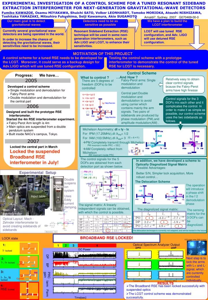
EXPERIMENTAL INVESTIGATION OF A CONTROL SCHEME FOR A TUNED RESONANT SIDEBAND EXTRACTION INTERFEROMETER FOR NEXT-GENERATION GRAVITATIONAL-WAVE DETECTORS Fumiko KAWAZOE, Osamu MIYAKAWA, Shuichi SATO, Volker LEONHARDT, Tomoko MORIOKA, Atsushi NISHIZAWA, Toshitaka YAMAZAKI, Mitsuhiro Fukushima, Seiji Kawamura, Akio SUGAMOTO 1 2 3 4 DP BP ITMp ITMi Amaldi7, Sydney, 2007 G070469-00-0 Our main goal is to detect gravitational waves Detectors need to be as sensitive as possible We have a plan to build the LCGT interferometer Currently several gravitational wave detectors are being operated in the world. In order to increase the chance of detecting the gravitational waves, their sensitivities need to be increased. Resonant Sideband Extraction (RSE) technique will be used in some next-generation interferometers, such as Adv.LIGO and LCGT, to enhance their sensitivities. LCGT will use tunedRSE configuration, and Adv. LIGO will use detuned RSE configuration. MOTIVATION OF THIS PROJECT A control scheme for a tuned RSE needs to be developed for the LCGT. Moreover, it could serve as a backup design for Adv.LIGO which will use tuned RSE configuration. Testing the control scheme with a prototype interferometer to demonstrate the control of the tuned RSE for LCGT is necessary. Control Scheme Progress: We have… What to control ? …And How ? Relatively easy to obtain clear control signals bcause the Fabry-Perot arms have high finesse 2005 Fabry-Perot arms: Single modulation and demodulation Central part:Double modulation and demodulation to avoid using carrier which contains mainly the arm signals. Two pairs of sidebands are pruduced by phase modulation (PM),and amplitude modulation(AM) . There are 5 degrees of freedom (DOFs) to be controlled • Developed a control scheme • Single modulation and demodulation for Fabry-Perot arms • Double modulation and demodulation for the central part Control signals for the 3 DOFs mix each other and it complicates the control. In order to make it as simple as possible, our control scheme uses the two sidebands as follows. 2006 • Designed and built the prototype RSE interferometer. • Started the 4m RSE interferometer experiment. • Fabry-Perot Arm length is 4m • Main optics are suspended from a double pendulum system • Built inside NAOJ’s campus, Tokyo. Michelson Asymmetry: dl = ly - lx For fPM (17.25MHz), dl /λPM=1/2 For fAM (103.5MHz), dl /λAM=3 (f2 = 6×f1) 2007 PM Completely transmit through Michelson PM resonant inside PRC + SEC Locked the central part in March Locked the suspended Broadband RSE interferometer in July! AM Conpletely reflect from Michelson AM resonant inside PRC The control signals for the 5 DOFs are obtained from each detection port as shown below. In addition, we have developed a scheme to Optically Diagnolized Signal Matrix Possible Advantages: Better S/N, Simpler lock acquisition, More robust control… Experimental Setup Double suspension system Uses Eddy current damping. The Delocation Scheme The operation will introduce a phase shift in the f 2 demodulation phase 30cm Input table 4m The signal matrix: A linearly independent signals can be obtained, with which the control is possible. The diagnolized signal matrix: Main interferometer The sensing matrix for the 3 DOFs can be diagnolized. Optical Layout: Mach -Zehnder interferometer to avoid creating sidebands of sidebands The delocation technique is currently not adapted, and will be tested in the future. BROADBAND RSE LOCKED! LOCK state CCD image when RSE is locked Optical Spectrum Analyzer Output 1: l- locked @PO @DP DC Power DP Next step is to lockthe arms with L+ and L- signal, which are currently controlled individually. 2: l-, l+ locked Carrier BP AM PM 3: l-. l+, ls PRC gain Carrier AM locked Frewuency [MHz] Frewuency [MHz] Iarm RESULTS 4: RSE locked • The Broadband RSE has been locked successfully with suspended optics Parm • The LCGT control scheme was demonstrated successfully. Time[sec]