Download
1 / 20
230 likes | 408 Views
Propulsion Train & Shaft Line Components. Introduction. Reduction Gears - fast to slow Lubrication System - overcome friction Shaft components - turbines to the working medium (ocean) Propeller - transform rotational energy into thrust. Reduction Gears. Purposes

E N D
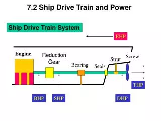
Introduction • Reduction Gears - fast to slow • Lubrication System - overcome friction • Shaft components - turbines to the working medium (ocean) • Propeller - transform rotational energy into thrust
Reduction Gears • Purposes • Allow turbine and propeller to operate at most efficient speeds • Combine two turbines to common shaft
Reduction Gears • Gear Types • Straight • excessive vibration • low power-transfer ability • Helical • Reduces vibration, quieter • Higher power transfer ability • Excessive axial thrust • Double Helical • Two sets of teeth cut at opposite angles • Eliminates axial thrust
Reduction Gears • Reduction Process • Pinion (small) gear drives reduction (large) gear • Reduction ratio = turns of pinion : turns of reduction gear • Double-reduction: reduction in 2 steps (more compact design) • For naval reduction gears, normally 30:1
Reduction Gears • Locked Train • Two sets of gears and shafts • Torque transmitted equally • Increases ability to transmit torque using smaller components • Turbine shafts connected to reduction gears by flexible couplings to allow for thermal expansion
Shaft Turning/Jacking Gear • Electric motor that rotates reduction gears, turbines, and shaft w/o using steam • Cool down turbines after operation • Prior to startup for even heating • Position for maintenance • Can be used to lock shaft in place • In event of casualty (i.e., loss of lube oil)
Shaft Bearings • Designed to support the moving parts of: • Shaft • Turbines • Thrust bearings • Absorb axial forces • Ex: Kingsbury Thrust bearing • Radial (Journal) bearings • Absorb radial forces
Lube Oil System • Provide lubrication and remove heat generated by bearings in overcoming friction • Major components: • Sump • Pump • Strainer • Cooler • Bearings Cooler SW Moving Parts Strainer Pump Sump
Lube Oil System • Lube oil can be kept in service for a long time if kept pure (two methods) • Batch Purification • In-port only • Uses heated settling tank • Continuous Purification • At-sea method • Centrifugal purifier separates oil & contaminants
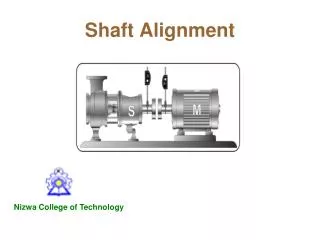
Propulsion Shaft • Shaft is hollow: reduces weight & increases resiliency • Consists of four sections • Thrust shaft - from thrust bearing in reduction gears to end of engineroom • Line shaft - located in shaft alley (supported by line shaft bearings) • Stern shaft - part of shaft which penetrates hull (supported by Stern Tube bearings) • Propeller shaft - shaft connected to propeller (supported by Strut Bearings)
Propulsion Shaft • Different sections needed for easy installation, removal, & maintenance
Propeller • Made of hub and blades & creates the thrust necessary to propel the ship through the water • Terms: • Pitch: axial distance advanced during one complete revolution of screw • Face: the pressure side • Back: the suction side
Propeller Types • Constant vs. Variable Pitch • Variable has the twisted look • Adv: more efficient over wide range of speeds • Fixed vs. Controllable Pitch • In controllable, blades can rotate on hub to change pitch (change direction) • Right vs. Left Hand Screw • Viewed from aft of ship • Twin-screw ships have one of each
Propeller • Cavitation • Formation and subsequent collapse of bubbles as propeller turns • Occurs at critical speed • Effects • Excessive noise • Erosion of blades • Decreased efficiency
Propeller Power vs. Shaft RPM • Flow a RPM; Thrust (head) a RPM2; Power a RPM3 • So, if 10% power yields 100 RPM, how much power will produce 200 RPM? 10% x% 1003 2003 x = 10 * (200/100)3 = 80% power
Sample Problems • Shaft hP • shp=2πNT/33,000 • Effective hP • Propulsive efficiency • Slip ratio


![An Introduction To Marine Steam Propulsion Plant [Source: US Navy]](https://cdn0.slideserve.com/482243/an-introduction-to-marine-steam-propulsion-plant-source-us-navy-dt.jpg)