Download
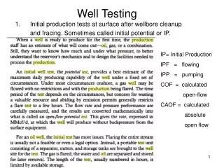
1 / 15
200 likes | 520 Views
Charge testing for well concept selection. November 2012. Eelco Bakker, Al Zanimonsky, NAM Mark Brinsden, Shell. EWAPS 12 - 6 Presented at 1 st European & W African Perforating Symposium, Amsterdam 7 – 9 November 2012. content. Well concept evolution Case for charge testing

E N D
Charge testing for well concept selection November 2012 Eelco Bakker, Al Zanimonsky, NAM Mark Brinsden, Shell EWAPS 12 - 6 Presented at 1st European & W African Perforating Symposium, Amsterdam 7 – 9 November 2012
content • Well concept evolution • Case for charge testing • Test set-up / test conditions • Charge test results • Findings charge testing • Impact concepts • Conclusions and way forward
Netherlands / Southern UK sector scene setting Mature area, remaining gas/oil accumulations small size (0.2 – 1 BCM) Early 2000’s: “step change” in costs required Well concept evolution Significant changes (down sizing) required in well design, rig selection, well functionality and surface lay-out in order to meet challenge
Typical well data Reservoir depths: 2800- 4600 mAH (1800 – 3500 m TVD) Reservoir pressure 250 – 360 bar (undepleted) Reservoir temperature 100 - 125 deg C permeability : <1 - 50 mD, porosity 8 - 20 % typical features: reduced csg sizes simple wellhead 3½” cemented completion 2” perf guns, static balanced / slight underbalance for trigger interval Concept worked for no. of years BUT next step ? Well concept evolution – 1st step current design Old design
Well concept evolution – the next step ? Proposed “slim” case, low permeability Proposed “slim” case, high permeability Current base case 3 ½” * 2 7/8” tbg, cemented in 4 7/8”- or 3 15/16” OH small guns: 1 9/16” or 1 11/16” 2 7/8” tbg, cemented in 4 7/8”- or 3 15/16” OH small guns: 1 9/16” or 1 11/16” 3 ½” tbg, cemented in 6” – or 4 7/8” OH 2” guns Driven by swell data assumptions
Slim well concept – impact gun size (base modelling) 2” guns IPR Small guns Case for charge testing: based on initial modeling, impact (Q / NPV) of changing to slim completion could be significant needs further clarification test DoP assumptions !!
Test set-up / test conditions Charge testing conditions in lab Field conditions Overburden = approx 9200 psi (634 bar) UCS of test sample Internal Pressure • In order to mimic field conditions as good as possible selected the following parameters: • Carbon Tan material (sandstone) • internal / confining stress • Section 2 only, no flow conditions • Various combinations OH size / tbg – and charge size • Varying cement thickness Confining stress on outside of the sample reservoir UCS = 1000 – 2000 psi (70 – 140 bar) Res Pressure = 4350 – 5000 psi (180 - 350 bar)
Charge test results 2” charge Data used in original modelling Sample no Sample no • Carried out some 33 tests (3 labs, test data randomly plotted !!) • Tests in 7” and 4” Carbon Tan cores, both centralised / excentralised. • In some tests free gun volume ( FGV) reduced to minimise effect DUB (dynunderbalance)
Charge test results small charge EHD, inch DoP, inch Sample no Data used in original modelling Sample no • Carried out some 17 tests (3 labs, test data randomly plotted !!) • Tests in 7” and 4” Carbon Tan cores, both centralised / excentralised. • In some tests FGV reduced to minimise effect DUB
Findings charge testing (1) • Futher analysis of results • Impact cement thickness clearly seen in majority of tests (6” vs 4 7/8” OH, 4 7/8” vs 3 15/16” OH) Sample no
Findings charge testing (2) • Futher analysis of results • Centralisation / stand-off impact: significant and hence to be included, not directly included in original modeling • Overall “perforation efficiency” (OH tunnel length/TCP tunnel length) from tests some 80%, hence efficiency for actual field conditions lower (less optimal conditions for dyn UB) tentatively set @ 50%
Impact charge testing on well concept selection • Impact 2” charge: • test results impact rel. minor • Higher DoP offset by lower assumed perforation eff. • Impact small charge: • impact clear • Lower DoP + lower assumed perforation eff.
“Economics” : Impact charge testing on well concept selection Small charge Major Impact BASE BASE 2” charge Minor Impact
Conclusions • Charge testing results • Reducing tubing size to 2 7/8” and using smaller charges not attractive given loss of inflow / recovery this concept no longer pursued !! • Impact perf tunnel efficiency significant • Impact cement thickness for smaller charges potentially under-estimated • potential impact on selected drilling practices (OH drilling diameter) • Perforation tunnel efficiency possibly overestimated in original modelling • “ideal” lab tests gave results of approx 80%, field conditions (small clearance, low static UB) far from ideal. • Way forward • Carry out gun survival tests for 2” guns inside 2 7/8” tubing if successful repeat charge testing pursue the tapered 2 7/8” * 3 ½” completion concept using 2” guns.