Download
1 / 16
190 likes | 734 Views
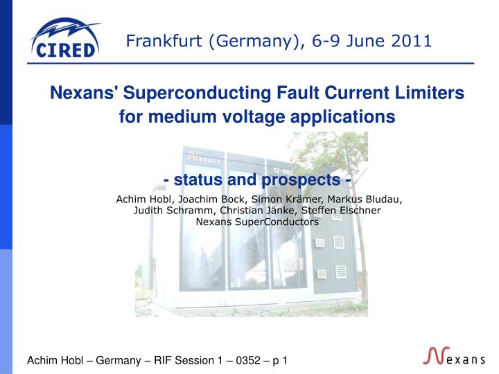
Nexans' Superconducting Fault Current Limiters for medium voltage applications - status and prospects - Achim Hobl, Joachim Bock, Simon Krämer, Markus Bludau, Judith Schramm, Christian Jänke, Steffen Elschner Nexans SuperConductors. Contents. Function of SFCL´s

E N D
Nexans' Superconducting Fault Current Limiters for medium voltage applications - status and prospects - Achim Hobl, Joachim Bock, Simon Krämer, Markus Bludau,Judith Schramm, Christian Jänke, Steffen Elschner Nexans SuperConductors
Contents • Function of SFCL´s • Possible installation sites • SFCL Systems • Perspectives for future grids
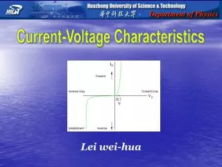
operating area HTS FCL normal operation limitation Operating area of HTS devices Transition fasterdue to temperature rise
Resistive Limitation FCL Breaker Load + compact + intrinsically safe + strong limitation + independent of short circuit level – current leads to low temperature
Inductive Limitation FCL Load + no quench of the superconductor + can be without interruption – large volume and weight – low level of limitation – relatively high impedance
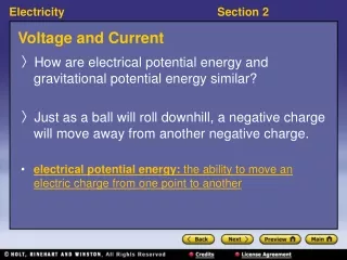
Function • ultrafast • reacts in 1-2 ms • automatic • no external trigger, • self-recovering • wear-free • service only for • cooling normal operation limiting operation
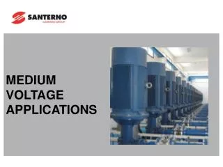
High voltage Transformer feeder Medium voltage Busbar coupler Installation sites • Bus bar coupling • In line (secondary side of transformer) • House load protection in power plants(auxiliary power) FCL FCL
Advantages of the FCL system • Passive limiting characteristics of the superconductor • Inherently safe and free from wear and maintenance • The power flow is not interrupted completely • Less mechanical and thermal stress Customer benefits • Higher network reliability • Considerable cost savings • Low impedance networks • Voltage stability and reduction of harmonics • Load levelling of busbars / transformers
12-400 (ASL 2) second system for UK (bifilar)Delivered to UK April 2011 FCL Systems 12-100 (ASL 1) first commercial systemField tested for ~8 months 12-800 (Vattenfall) first system in a power stationField tested Nov. 2009 - Dec. 2010 XX-YYY XX: Voltage [kV] YYY: Current [A]
12-100 ASL, Newcastle ENW, Bamber Bridge Live on grid10-2009 to 06-2010
Test at IPH 12-400 Customer has ordered second system!
12-800 Power Plant Boxberg, Germany Supply for crushers and conveyor belts
Perspectives for future grids • Low impedance networks WITH low short circuit power • Supports integration of distributed generation • Load / generation growth without substation upgrading • Improvements in availability and stability
generator transformer FCL 10 kV G 5...50 MVA Integration of distributed generation 110 kV 10 kV grid
powersafetyat its best thank you for your attention