Download
1 / 18
220 likes | 678 Views
Learn about the properties of thin lenses, ray tracing techniques, thin lens equation, and magnification in optical devices such as cameras, the human eye, corrective lenses, telescopes, and microscopes, exploring lensmaker’s equation, and lens aberrations.

E N D
Outline • Thin Lenses; Ray Tracing • The Thin Lens Equation; Magnification • Combinations of Lenses • Lensmaker’s Equation • Cameras: Film and Digital • The Human Eye; Corrective Lenses • Magnifying Glass • Telescopes • Compound Microscope • Aberrations of Lenses and Mirrors
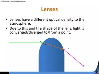
Thin Lenses; Ray Tracing Thin lenses are those whose thickness is small compared to their radius of curvature. They may be either converging (Fig. a) or diverging (Fig. b). Fig. b Fig. a
Thin Lenses; Ray Tracing Thin lens:A lens with a small thickness compared to the radius of curvature. May be either Converging (Fig. a) or Diverging(Fig. b)
Converging Lens A lens that is thicker in the center than at the edge. Parallel rays are brought to a focus by a converging lens.
Diverging LensA lens that is thicker at the edge than in the center. A diverging lens makes parallel light diverge. The focal point is that point where the diverging rays would converge if they were projected back.
The Power of a lens is defined to be the inverse of its focal length: Lens Power is measured in diopters, D: 1 D 1 m-1.
Image Formation by Converging Lenses • Just as for mirrors, for lenses,Ray diagramsare used to determine where an image will be. For lenses,3 key rays, each beginning on the object, are used: • Ray 1:Comes in parallel to the axis & exits through the focal point. • Ray 2:Comes in through the focal point & exits parallel to the axis. • Ray 3:Goes through the center of the lens & is undeflected. • See the figures on the next slide!
Three key rays, each beginning on the object, are used: Ray 1: Leaves a point on the object going parallel to the axis & refracts through focal point F behind the lens. Ray 2: Leaves a point on the object, passes through F' in front of the lens & refracts parallel to the axis behind it. Ray 3: Leaves a point on the object & passes through the lens center.
Conceptual Example A half-blocked lens. What happens to the image of an object if the top half of a lens is covered by a piece of cardboard (Fig. a)? Fig. a Fig. b Answer:An image will still be visible, but it will be less bright than it would be without the blockage. (Fig. b)
To analyze a diverging lens, use The same 3 Rays. The image will be upright and virtual.
The Thin Lens Equation; Magnification The thin lens equation is similar to the mirror equation:
The Sign Conventions are slightly different for lenses than for mirrors. • The focal length is positive for converging lenses & negative for diverging lenses. • The object distance is positive when the object is on the same side as the light entering the lens (not an issue except in compound systems); otherwise it is negative. • The image distanceis positive if the image is on the opposite side from the light entering the lens; otherwise it is negative. • The height of the image is positive if the image is upright & negative otherwise.
The Magnification Formula is also the same as that for a mirror: The power of a lens is positive if it is converging and negative if it is diverging.
Problem Solving Thin Lenses • Draw a ray diagram.The image is located where the key rays intersect. • Solvefor the unknowns. • Follow the sign conventions. • Check that your answers are consistent with the ray diagram.
Example Image formed by converging lens. Calculate(a)The Position, & (b)The Size, of the image of a 7.6-cm-high leaf placed 1.00 m from a +50.0-mm focal-length camera lens.
Example: Object close to a converging lens.An object is placed 10 cm from a 15-cmfocal-length converging lens.Calculate the Image Position & Size(a) Analytically, & (b) Using a ray diagram.
Example: Diverging lens. Where must a small insect be placed if a 25-cm focal-length diverging lens is to form a virtual image 20 cm from the lens, on the same side as the object? See the figure.