Download
1 / 68
740 likes | 960 Views
Inertial Tracking and Indoor Mapping. Guobin (Jacky) Shen Microsoft Research Asia Mobile Location Sensing Tutorial, Mobisys’13. Outline. Brief introduction to particle filtering Personalized inertial tracking Indoor mapping via tracking and landmarks. Brief intro to Particle filtering.

E N D
Inertial Tracking and Indoor Mapping Guobin (Jacky) Shen Microsoft Research Asia Mobile Location Sensing Tutorial, Mobisys’13.
Outline • Brief introduction to particle filtering • Personalized inertial tracking • Indoor mapping via tracking and landmarks
Particle filter • Particle filtering is a method for state estimation, can handle nonlinear models with non-Gaussian noise, is a Monte Carlo method • The probability density function is approximated using point weights • Each point is called a particle, has a positive weight • The particle filter gives an approximate solution to an exact model, rather than the optimal solution to an approximate model.
Basic algorithm • Initialize (distribute particles) • Time update (move particles) • Measurement update (change weights) • Resample (if needed) • Goto 2 when new measurement arrives
Time Update • One-step prediction of each particle • Note that a realization of the process noise is used for every particle.
Measurement update • The weights are adjusted using the measurement • All weights are normalized • Particles that can explain the measurement gain weight • Particles far off the true state lose weight. • The density of the cloud changes
Resampling • It can be shown that the algorithm degenerates • All particles but one become very light • Solved by resampling so that all weights become equal
Implementation • The approximation error decreases as the number of particles grow • Computational complexity is proportional to the number of particles • N can easily be changed during runtime. • Variants of the particle filters exist
Personalized Inertial Tracking Fan Li, et al., Reliableand Accurate Indoor Localization Using Phone Inertial Sensors, Ubicomp’12.
Motivation • Growing demand for fine-grain indoor localization • Indoor navigation • Mobile advertising • Mobile social network • But indoor localization is not yet common place… • Infrastructure-based • WiFi, RF Beacons (BLE, ultrasound, FM) • Inertial sensors based • Numerous prior art, using wearable sensors • e.g., Woodman&Harle’08, Klingbeil&Wark’08
Approach and Requirements • Approach: leverage mobile phone sensors and perform inertial-based tracking • Growing adoption of sensor-enabled smartphones • Infrastructure independent • Requirements: • Using existing on-device sensors only • Phone position free • Meter level accuracy • Energy efficiency
System Architecture 1 1 Step Detector 3 2
Robust Step Detection • Three stages • Phone position free • Only use magnitude of 3-axis accelerometer
Enhanced Peak detection Fake Peak Fake valley
Dynamic time warping validation • Waveform will repeat at every two steps left Right left Right left No Yes Yes is a step
System Architecture 1 3 2 2 Heading estimator
User heading inference • Case 1: Held In-hand • Case 2: In-pocket –Dynamic offset People’s heading The direction of phone’s Y axis
User heading inference • Initial orientation inference • Heading updating • Heading adjustment No Particle died? Update direction initialize Yes Adjust heading direction when particles died
Initial orientation inference • Assume initially, the phone heading is the same as the direction of the face • When the phone is put into the pant pocket, the transformation is given by:
Update heading direction • Update direction at the so-called inference points • Assumption: Phone heading is relatively stable with leg movements
Adjust heading direction via map constraint Mitigate the effect of inaccuracies in heading sensor reading
System Architecture 1 3 3 Step model 2 Personalization
Generic vs. personalized model All users User 3 User 11 User 23 Step length model: ;
Personalization Framework • Initialize the particle filter with generic model • Adapt to a personalized model at the first turn • Continuously refine the personalized model at subsequent turns via particle filtering
Step model refinement Turn? Yes • Compute new model based on
Particle filter • Particle state: <> • Particle propagation • Correction • Particles can’t cross a wall • follow certain zero-mean • distribution (e.g., normal dist.)
Step detection - result NSC: Nokia step counter on Symbian; PED: Pedometer on iPhone NW: Noomwalk step counter on Android; PHD: Enhanced peak detection + DTW Standing Still Scenario Unconstrained Walking Scenario • Enhanced Peak detection outperforms existing • commercial solutions
Heading accuracy • Proposed heading adjustment approach significantly reduces heading error, closely follows ground-truth heading
User trajectory estimation without personalization with personalization Estimated trajectory Ground truth • Personalization allows estimated user trajectories to closely match ground-truth
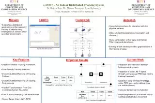
Inertial tracking for wifi Training sample collection AnshuiRai, et al., Zee: Zero-Effort Crowdsourcingfor Indoor Localization, Mobicom’12
WiFi Based Localization • Step 1: Site survey • To obtain training data <location, RSS> • Usually a manual process by specialist • Step 2: Offline training phase • Mapping: location RSS • Step 2: Online location inference • Inverse mapping: RSS Location Often key bottleneck
Basic idea • Tackle the task via crowdsourcing • Leverage normal user walking and mobile sensors • Personalized inertial tracking and background WiFi data collection • Requirement: No user inputs
Problem and Solution • Problem: to get the location of each WiFi scan. • Solution: personalized inertial tracking Stride Length Distance Use WiFi card to scan and obtain measurements simultaneously Use motion vectors to track the users’ location as they walk Step Accel Motion Vector Direction of Motion Compass
Challenges • Unknown initial location • No input from user, nor intermediate checkpoints • Unknown stride length • No user specific pre-calibration • Unknown phone placement • In hand, pant pocket, etc. • Compass heading errors Personalized inertial tracking
Challenge: unknown initial location • No input from user, no intermediate checkpoints A C B 35m D 65m
Solution: belief back propagation • Trace the probability distribution backwards in time 65m 35m
Challenge: heading offset estimation • Walking direction ≠ Compass Direction • Real Heading = Compass Measurement () + Placement Offset () (Constant) + Magnetic Offset () (Var, Gaussian) • Estimating placement offset • Key Observation: Second harmonic is absent in acceleration perpendicular to walking direction
Walkie-Markie Landmarks & Indoor Mapping Guobin Shen, et al., Walkie-Markie: Indoor Mapping Made Easy, NSDI’13.
The context of this work … • Location, location, location, … • Primarily focused on location inference algorithms • Largely neglected the fundamental “enabler” – Maps! • “… assume the radio map is established offline in advance …” • Such assumptions are not easy to fulfill, in practice.
Internal pathway map is of practical interest • Maps = { floor plan, radio map, … } • Localizing users w.r.t pathways is of practical importance • Users move along pathways • Indoor locations (POIs) are connected via pathways
Problem & high-level approach • How to build internal pathway maps for millions of buildings? • Professional onsite survey? – Expensive and not scalable • Request floor plans? – Impractical • Different owners, often proprietary, legacy buildings, frequent redecoration, etc. • Still missing hooks for localization • Pathway mapping via user tracking and crowdsourcing! • User trajectory consists of portions of pathways • Possible to infer pathway maps from enough user trajectories • Dead Reckoning is possible with phone IMU-sensors
Goal and challenges • Build a crowdsourcing system that can construct indoor pathway maps by ordinary pedestrians w/ mobile phones. • Challenges: • Noisy IMU-based tracking results, and significant drift over time • Difficult to fuse data from different users • Start/stop anywhere, cover only a subset • Must handle user diversity and device diversity • Automatic, no special user attention, no change to user behavior
Core concept: phone perceivable landmark • Motivating observation: landmarks • Real life UX – people give directions w.r.t landmarks • Landmark: easily discoverable, stable, and at known location • Landmark can stoperror propagation and merge different paths • Phone perceivable pathway mark • A stablelocation on the pathway that can be automatically discoveredand unambiguously identifiedby mobile phones with its on-device sensors • Visual landmarks: good for human, but not easily discoverable by devices! Cell Tower GPS Bluetooth Accelerometer Compass Microphone Camera
Leverage WiFi Infrastructure for landmarks • Wide deployment of WiFi infrastructure • Using AP? – Coverage overly large, unknown position • Using WiFi fingerprints? • Good association between WiFi fingerprints and locations • Basis for state-of-the-art WiFi-based localization methods • Challenges: • Difficult to model WiFi signal accurately • WiFi signal fluctuates over time, affected by multipath effects • Difficult to deal with device diversity • Different readings for the same WiFi signal on different devices
WiFi-defined landmark (WiFi-Mark) - Key idea: don’t look for AP, look for its ‘shadow‘ on pathways The mobile phone constantly measures received WiFi signal strength (RSS) while walking along a pathway AP Pathways RSS increases or decreases when approaching or leaving an Access Point (AP). -- law of radio propagation The location corresponding to the tipping point of RSS trend is a WiFi-defined landmark. -- a novel way to leverage WiFi RSS Many such landmark opportunities exist. Displacement AP Coverage
Feasibility of WiFi-Mark • Measurement study • Straight corridor 35m in length, two devices, very slow motion • Different time of day (morning, afternoon, evening, midnight) • Filtering with triangle window • Invariant location, over ToD stable and consistent • Obvious trend easily discoverable by device • Using trend, not value insensitive to device type, device attitude
How to uniquely identify each WiFi-Mark? • Large number of potential WiFi-Marks: O(#AP x #Pathways) • Using AP identification (BSSID) is not enough • One AP can lead to multiple WiFi-Marks • Some good, some indistinguishable, and some false case AP3 2 3 PW1 1 4 5 AP2 AP1 PW3 PW2 7 6
WiFi-Mark qualification and identification in effect • Three-element tuple • BSSID of the master AP • Orientations, before and after the RSS tipping point • Neighborhood APs Master AP (BSSID) Neighbor AP1 Neighbor AP2 WiFi-Mark: [BSSID, Orientation<before, after>, Neighboring APs<(BSSID, DRSSI)>]