Download
1 / 43
430 likes | 537 Views
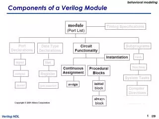
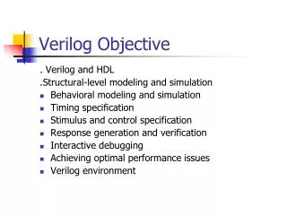
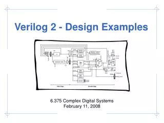
Introduction to Verilog (Behavioral Modeling). Agenda. Gate Delays and User-Defined Primitives Behavioral Modeling Design Examples Hands-on Practice. Gate Delays and User-Defined Primitives. Compiler directive. Unit of measurement. Round-off unit. Gate Delays.

E N D
Agenda • Gate Delays and User-Defined Primitives • Behavioral Modeling • Design Examples • Hands-on Practice
Compiler directive Unit of measurement Round-off unit Gate Delays • Physical circuits exhibit propagation delay • Therefore, necessary to specify delays in simulation • Association of time unit with Physical time through compiler directive ‘timescale 1ns/100ps What if no timescale is specified?
Gate-level model with propagation delays module cct_prop_delay(A,B,C,D,E) output D,E; input A,B,C; wire w1; and #(30) G1(w1,A,B); not #(10) G2 (E,C); or #(20) G3 (D,w1,E); endmodule
User-Defined Primitives • UDP and system primitive • UDP specification in terms of tabular form Rules for defining primitives • Keyword pair ---- primitive and endprimitive • One output listed first in the port list • The order of the inputs must conform with the one in the table that follows • Truth table keyword pair--- table and endtable • Values of inputs ending with colon following an output
Verilog model: (OR Gate) primitive UDP_123(C,A,B); output C; input A,B; table // A B : C 0 0 : 0; 0 1 : 1; 1 0 : 1; 1 1 : 1; endtable endprimitive
LED Decoder Design Seven Segment LED seg0 LED DECODER seg6 seg1 switch1 seg2 seg5 seg4 seg3 switch2 seg3 switch3 seg2 seg1 seg4 seg5 seg0 seg6
Verilog module module test8bit(switch,seg); input [2:0]switch; output [7:0]seg; • reg [7:0] seg; • always @(switch) • begin • case(switch) • 3'b000: seg=8'b01110111; • 3'b001: seg=8'b00010010; • 3'b010: seg=8'b01011101; • 3'b011: seg=8'b01011011; • 3'b100: seg=8'b00111010; • 3'b101: seg=8'b01101011; • 3'b110: seg=8'b01101111; • 3'b111: seg=8'b01010010; • endcase • end endmodule
The Translate process converts the netlist output by the synthesizer into a Xilinx-specific format and adds with it the design constraints specified by user. • The Map process decomposes the netlist and rearranges it so it fits nicely into the circuitry elements contained in the specified FPGA device. • Then the Place & Route process assigns the mapped elements to specific locations in the FPGA and sets the switches to route the logic signals between them.