Download
1 / 1
10 likes | 119 Views
Trajectory Optimization to Delay Transition for Mars Entry Aeroshells Roman Jits , ELORET Corporation/NASA Ames Research Center David Saunders, ELORET Corporation/NASA Ames Research Center IPPW-7, Barcelona, June 2010.

E N D
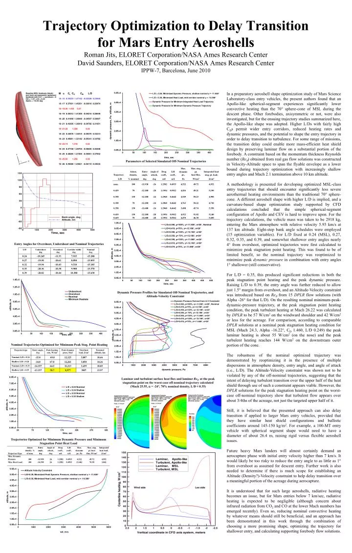
Trajectory Optimization to Delay Transition for Mars Entry AeroshellsRoman Jits, ELORET Corporation/NASA Ames Research CenterDavid Saunders, ELORET Corporation/NASA Ames Research CenterIPPW-7, Barcelona, June 2010 • In a preparatory aeroshell shape optimization study of Mars Science Laboratory-class entry vehicles, the present authors found that an Apollo-like spherical-segment experiences significantly lower convective heating than the 70° sphere-cone of MSL during the descent phase. Other forebodies, axisymmetric or not, were also investigated, but for the ensuing trajectory studies summarized here, the Apollo-like shape was adopted. Higher L/Ds with fairly high CDs permit wider entry corridors, reduced heating rates and dynamic pressures, and the potential to shape the entry trajectory in order to delay transition to turbulence. For some range of missions, the transition delay could enable more mass-efficient heat shield design by preserving laminar flow on a substantial portion of the forebody. A constraint based on the momentum thickness Reynolds number (Re) obtained from real gas flow solutions was constructed in Velocity-Altitude space to span the flyable envelope as a lower bound during trajectory optimization with increasingly shallow entry angles and Mach 2.1 termination above 10 km altitude. • A methodology is presented for developing optimized MSL-class entry trajectories that should encounter significantly less severe aerothermal heating environments than the traditional 70° sphere-cone. A different aeroshell shape with higher L/D is implied, and a curvature-based shape optimization study supported by CFD calculations concluded that the simple spherical-segment configuration of Apollo and CEV is hard to improve upon. For the trajectory calculations, the vehicle mass was taken to be 2918 kg, entering the Mars atmosphere with relative velocity 5.93 km/s at 137 km altitude. Eight-step bank angle schedules were employed (15 optimization variables). For L/D fixed at 0.24 (MSL), 0.27, 0.32, 0.35, and 0.39, and somewhat shallower entry angles nearly 4° from overshoot, optimized trajectories were first calculated to minimize peak stagnation point heating. This was found to be of limited benefit, so the nominal trajectory was reoptimized to minimize peak dynamic pressure in combination with entry angles 1° shallower (still conservative). • For L/D = 0.35, this produced significant reductions in both the peak stagnation point heating and the peak dynamic pressure. Raising L/D to 0.39, the entry angle was further reduced to allow just 1.5° margin from overshoot, and an Altitude-Velocity constraint was introduced based on Re from 15 DPLR flow solutions (with Alpha -26° for that L/D). On the resulting nominal minimum-peak-dynamic-pressure trajectory, at the peak stagnation point heating condition, the peak turbulent heating at Mach 26.22 was calculated by DPLR to be 57 W/cm2 on the windward shoulder and 42 W/cm2 or less for the acreage. For comparison, according to comparable DPLR solutions at a nominal peak stagnation heating condition for MSL (Mach 24.3, Alpha ‑16.22°, CD 1.460, L/D 0.249) the peak laminar heating is about 55 W/cm2 (on the nose) and the peak turbulent heating reaches 144 W/cm2 on the downstream outer portion of the cone. • The robustness of the nominal optimized trajectory was demonstrated by reoptimizing it in the presence of multiple dispersions in atmosphere density, entry angle, and angle of attack (i.e., L/D). The Altitude-Velocity constraint was shown not to be violated by any of the off-nominal trajectories, suggesting that the intent of delaying turbulent transition over the upper half of the heat shield through use of such a constraint appears viable. However, the DPLR solutions for the peak stagnation heating point on the worst-case off-nominal trajectory show that turbulent flow appears over about 3/4ths of the acreage, not just the targeted upper half of it. • Still, it is believed that the presented approach can also delay transition if applied to larger Mars entry vehicles, provided that they have similar heat shield configurations and ballistic coefficients around 145-150 kg/m2. For example, a 100-MT entry vehicle with spherical segment shape would need to have a diameter of about 26.4 m, raising rigid versus flexible aeroshell issues. • Future heavy Mars landers will almost certainly demand an aerocapture phase with initial entry velocity higher than 7 km/s. It would likely be too risky to reduce the entry angle to as little as 1° from overshoot as assumed for descent entry. Further work is also needed to determine if there is much scope for establishing an Altitude (Density?)-Velocity constraint to help delay transition over a meaningful portion of the acreage during aerocapture. • It is understood that for such large aeroshells, radiative heating becomes an issue, but for Mars entries below 7 km/sec, radiative heating is expected to be negligible (although concern about infrared radiation from CO2 and CO at the lower Mach numbers has emerged recently). Even so, reducing nominal convective heating by whatever means should still be beneficial, and an approach has been demonstrated in this work through the combination of choosing a more promising shape, optimizing the trajectory for shallower entry, and calculating supporting forebody flow solutions. M CL CD CM L/D 18 -16 0.35233 1.47142 -0.03308 0.23945 18 -17 0.37001 1.45251 -0.03616 0.25474 18 -18.00 1.433 0.27 18 -19 0.40312 1.41200 -0.04216 0.28549 18 -20 0.41849 1.39049 -0.04507 0.30097 18 -21 0.43305 1.36819 -0.04792 0.31651 18 -21.22 1.358 0.32 18 -22 0.44676 1.34515 -0.05070 0.33213 18 -23 0.45961 1.32142 -0.05341 0.34782 18 -23.14 1.318 0.35 18 -24 0.47158 1.29704 -0.05605 0.36358 18 -25 0.48265 1.27205 -0.05861 0.37942 18 -25.66 1.256 0.39 18 -26 0.49280 1.24651 -0.06110 0.39535 Parameters of Selected Simulated Off-Nominal Trajectories Entry Angles for Overshoot, Undershoot and Nominal Trajectories Dynamic Pressure Profiles for Simulated Off-Nominal Trajectories, and Altitude-Velocity Constraint Nominal Trajectories Optimized for Minimum Peak Stag. Point Heating Laminar and turbulent surface heat flux and laminar Re at the peak stagnation point on the worst-case off-nominal trajectory calculated (Mach 25.55, = -24°, 70% nominal density, L/D ≈ 0.35) Trajectories Optimized for Minimum Dynamic Pressure and Minimum Stagnation Point Heat Load


![C [0]](https://cdn1.slideserve.com/3218926/slide1-dt.jpg)