Download
1 / 54
550 likes | 782 Views
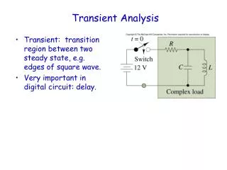
HVDC Modeling and Analysis in Transient Stability. March 18, 2014 Kate Davis, Ph.D. HVDC Lines and Stability. HVDC l ines can rapidly control the transmitted power so they need to be modeled in transient stability. Rectifier Terminals. Inverter Terminals. HVDC Overview.

E N D
HVDC Modeling and Analysis in Transient Stability March 18, 2014 Kate Davis, Ph.D.
HVDC Lines and Stability • HVDC lines can rapidly control the transmitted power so they need to be modeled in transient stability Rectifier Terminals Inverter Terminals
HVDC Overview • HVDC lines are often configured using a bipolar link • Made up of groups of transformers, converters, and filters • Modeled as a single record, two-terminal DC line, in transient stability software • Each terminal has two converters of equal rating • The junction between the converters is grounded • Normally, there is no ground current
Transient Stability Modeling Reference • The most comprehensive book on this type of analysis is by PrabhaKundar and is called Power System Stability and Control published in 1994. • Book is too detailed for a classroom textbook, but it is a really great as a reference book once you’re working • Covers HVDC Transmission
Three-Phase Bridge Converter • Converters control the power flow through the HVDC link • Refer to any power electronics book • For this analysis, assume • Ideal AC voltage source in series with inductance • Direct current Id is ripple free due to smoothing reactor • Ideal switches
Simplified Bridge Model • Switches are labeled in firing order
Bridge Firing Order Va is more positive than Vb and Vc, 1 conducts Vb is more negative than Vc and Va, 6 conducts Output voltage is eab
Bridge Firing Order Va is more positive than Vb and Vc, 1 conducts Vc is more negative than Va and Vb, 2 conducts Output voltage is eac
Bridge Firing with a Delay Angle • Firing can be delayed by α, causing current to lag the voltage Rectified DC voltage, no firing angle = Rectified DC voltage, firing angle
Power Factor Angle • As α varies, the phase displacement between the voltage and current also varies • 0<α<90, P decreases and Q increases
Power Factor Angle • The converter always draws reactive power from the AC system • α=90, P is zero, Q is max • 90<α<180, P increases, Q decreases
Commutation Overlap • The analysis so far assumes there are always exactly two switches on at one time • In reality, there is some overlap • Denoted by commutation angle µ • 0<µ<60, typically µ is 15 to 25 • Commutation begins after α and ends after extinction angle δ=µ+α • Source inductances matter here
Commutation Overlap • Voltage Waveforms • Effect of commutation overlap is a voltage drop
Rectifier vs. Inverter • With no commutation overlap, the converter becomes an inverter at ==90 • With commutation overlap, this occurs later, • The converter transitions at • The direct current from the rectifier to inverter • Resistances are small, so small changes in voltage can have a large impact on current!
Summary of Angles • Rectifier • Inverter • Control of voltage and current (or power) is achieved by controlling the internal voltages and • Control firing angles (fast) or tap changers (slow) • Typically the rectifier maintains the DC current and the inverter maintains the DC voltage
Generic PowerWorld Converter Model Fixed parameters and setpoints of the converter
Generic Converter Model Limiting parameters of the converter Variables calculated in AC power balance equations Variables calculated in DC system
Generic DC Network • A completely general multi-terminal DC network can be modeled • Challenge is fault clearing
Generic DC Network • Each converter is given a setpoint: voltage, current, or power • Only one bus can have a voltage set point • Solve using Newton’s method • Assumes unconstrained operation • Then account for limits and update AC equations
Multi-Terminal DC Line Dynamic Model for the Pacific DC Intertie
PDCI Model Now only one converter here
PDCI Model • Documentation • Existing text files contained the actual user-defined model implementation of the PDCI model (pdci_ns3.p and pdci_sn3.p) • Dmitry Kosterev provided partial documentation describing the pdci_sn3.ps file. Most helpful for the newer CELILO 500 kV converters which had recently been upgraded • PowerWorld took the actual 1,300 lines of code in the pdci_ns3.p file and determined the block diagram being modeled for this important device (also looked through pdci_sn3.p) • The pdci_ns3.p code encompasses a model for controlling the firing angle on two converters at Celilo and one converter at Sylmar
PowerWorld Implementation and User Experience • Code Implementation • Simulator’s internal code has been written to make the interaction of the dynamic multi-terminal DC line model and converters with the network boundary equations generic • This will make adding new DC line models much easier • Also will permit the creation of an interface to a user-defined multi-terminal DC line model • For immediate use, the user need only check a box asking that this model be used • Simulator will look for the PDCI in the case and automatically include the dynamic model if appropriate • All parameters of the model are hard-coded then • Version 17 allows the user to explicitly add the dynamic models and also see the internal states of these models if desired • All parameters of the model will remain hard-coded for model • May change this eventually if desired
Implementation Overview in Simulator • Assign dynamic model MTDC_PDCI to the multi-terminal DC Line record • Assign appropriate dynamic converter models to the various DC converters: CONV_CELILO_E, CONV_CELILO_N, CONV_SYLMAR
MTDC_PDCI • The model is assigned to one Multi-Terminal DC record • For the PDCI, two separate MTDC records are modeled, one for each pole of the PDCI • Inputs • From DC Converters: States of the sensed DC Current, DC Voltage, and AC Voltage at each converter • AC Network: Direct access to network boundary equation AC voltages is also used • Other MTDC_PDCI: There is some feedback between the two poles in the DC voltage measurement • Outputs • Feeds a reference current to each DC Converter model: id_ref_CN, id_ref_CE, and id_ref_S • Also feeds a flag for VacLow as needed to the CONV_CELILO_N
MTDC_PDCI:Low Voltage Detection Average DC voltage across both poles of the MTDC
MTDC_PDCI:Parameters and Initialization • Parameters and initialization depends on flow direction on the PDCI (North to South) or (South to North)
CONV_CELILO_E • Model assigned to the converter at the 230 kV bus at Celilo – the “Existing” Control • Inputs • Reference current id_ref_CE from MTDC_PDCI • Network boundary equation converter values: Idc, Vdc, Vac • Output • Cosine of the control angle (Alpha or Beta as appropriate)
CONV_CELILO_EParameters and Initialization • Parameters and initialization depends on flow direction on the PDCI (North to South) or (South to North)
CONV_CELILO_N • Model assigned to the converter at the 500 kV bus at Celilo – the “New” Control • Inputs • Reference current id_ref_CN from MTDC_PDCI • VacLow from MTDC_PDCI • Network boundary equation converter values: Idc, Vdc, Vac • Output • Cosine of the control angle (Alpha or Beta as appropriate)
CONV_CELILO_NParameters and Initialization • Parameters and initialization depends on flow direction on the PDCI (North to South) or (South to North)
CONV_SYLMAR • Model assigned to the converter at the Sylmar • Inputs • Reference current id_ref_S from MTDC_PDCI • Network boundary equation converter values: Idc, Vdc, Vac • Output • Cosine of the control angle (Alpha or Beta as appropriate)
CONV_SYLMARParameters and Initialization • Parameters and initialization depend on flow direction on the PDCI (North to South) or (South to North)
Handling of the Interaction with Network Boundary Equations • DC Converter equations • Written in terms of Alpha at rectifiers • Written in terms of Beta at inverters • “Beta” is different than the Gamma traditionally used when writing the static power flow equations • Equations are as follows • Also force currents to be positive
What is Different Than a Power Flow Solution? • In static power flow solutions, DC converter control is instantaneous • Power Flow Firing Angles (Alpha and Gamma) are assumed to move instantaneously • PDCI model does not make this assumption, it models the dynamics of the firing angle control • Power flow solutions also ignore the inductance of the DC transmission line • In power flow, DC currents change instantaneously • PDCI models inductance, so DC currents become state variables • Note: can also be capacitance in the DC transmission lines • We are NOT modeling in the PDCI presently • For cable DC lines (underwater for instance), the capacitance may become large enough that modeling will be important
Traditional Explicit Numerical Integration Routines • Always use the initial algebraic variables to back-solve and obtain the initial values of all dynamic states • PowerWorld’s transient stability tool then uses explicit integration (2nd order Runga-Kutta) • Use numerical integration (with a time-step) to update dynamic state • Update algebraic variables such as the AC system voltage and angle (by solving network boundary equations) • Go back to 2 and repeat until simulation finished • Multi-terminal DC simulation will be inserted between steps 1 and 2
Implementation in Numerical Solution Engine of MTDC • Numerical integration integrate the MTDC_PDCI, CONV_CELILO_E, CONV_CELILO_N, and CONV_SYLMAR model states • Updated variables are cos() and cos() • Take the cos() and cos() terms and use them to model a step change in the DC voltages seen by the DC network equations. Use numerical integration to solve for new DC voltages and DC currents • Updated variables are DC voltage and DC Currents • Solving normal AC network boundary equations except modify DC line equations to assume that cos() and cos() , and DC currents are a constant. When network boundary equations are solved update the DC voltages • Updated variables are DC voltages • Back to Step 1 and repeat
Step 2: Numerical Integration of DC Network Equations • DC Converter Model • Constant angle so model asa constant voltage source • DC Transmission Line Model • Model as RL circuit using trapezoidal rule • DC Bus Equation • Just use Kirchoff’s Current Law
Step 2: Numerical Integration of DC Network Equations • Solve the previous set of equations using sub-interval integration • Assume at beginning that no converters are stuck at the zero current limit • At each sub-interval, if the calculation yields a converter current with the wrong sign then redo the sub-interval replacing the DC converter equation with the equation I=0 • Assume that once a current goes to zero it remains zero during the remaining sub-interval time-steps