Download
1 / 44
870 likes | 1.97k Views
Structural Modeling of Post-Tensioning Tendons Dr. Bijan O. Aalami Emeritus Professor, San Francisco State University Principal, ADAPT Corporation, Redwood City, Ca. FLAT DUCT GROUTED POST-TENSIONING. Ngee Ann City, Singapore - BBR. UNBONDED POST-TENSIONING CONSTRUCTION.

E N D
Structural Modeling of Post-Tensioning Tendons Dr. Bijan O. Aalami Emeritus Professor, San Francisco State University Principal, ADAPT Corporation, Redwood City, Ca
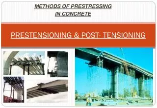
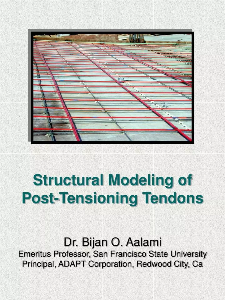
FLAT DUCT GROUTED POST-TENSIONING Ngee Ann City, Singapore - BBR
UNBONDED POST-TENSIONING CONSTRUCTION Red Lion Inn Hotel Modesto, California
GENERIC ANCHORAGE DEVICE ( 5") 127mm 57mm ( 2.25") (a) PLAN 38mm ( 1.50") (b) SECTION 33mm ( 1.30") (c) WEDGE
UNBONDED TENDON ANCHOR DEVICE ASSEMBLY 12.7 mm (0.5"*) PLASTIC CORROSION WIRE SHEATHING INHIBITING COATING NOTE: * NOMINAL DIAMETER (a) STRAND (b) TENDON GREASE FILLED PLASTIC CAP TUBE SHEATH STRAND (c) ANCHORAGE ASSEMBLY
ARRANGEMENT OF UNBONDED POST-TENSIONING SYSTEM
FUNCTION OF POST-TENSIONING TENDON • Uplift • Counteract selfweight • Precompression • Mitigate cracking • Reduce Deflection • Add Strength
Prestressing Tendon’s Contribution depends on: • Local stress in tendon • At service condition • At strength limit state • Profile of tendon (geometry) • Tendon Cross Section
CRITICAL CONSIDERATION IN STRUCTURAL MODELING OF TENDONS • Immediate loss of stress • Friction loss • Seating loss (draw-in) • Elastic shortening • Long-term losses • Relaxation in prestressing • Shrinkage in concrete • Creep in concrete • Others, such as • Change in stress due to flexing of member under applied loading • Aging of concrete • Temperature
LOSS OF PRESTRESSING FORCE DUE TO FRICTION AND SEATING STRESSING END TENDON DEAD END (a) TENDON GEOMETRY F AVERAGE FORCE F TENDON FORCE o F x x (b) TENDON FORCE PROFILE
TENDON MODELING • As an Applied Loading • As a Load Resisting Element
TENDON MODELING AS APPLIED LOADING • Simple load balancing [T Y Lin, 1981] • Extended Load Balancing [Aalami, 1990] • Modeling Through Primary Moments • Modeling Through Equivalent Forces
15 kN/m 11.76 kN/m 97.84 60 151.73 (b) BALANCED LOADING SIMPLE LOAD BALANCING 20m 12m PARABOLIC TENDON 100 1200kN 800 400 400 60 300 700 (a) PROFILE IDEALIZED AS PARABOLA
SIMPLE LOAD BALANCING 1.2 6 10 8 2 4.8 400 400 300 60 700 (a) REVERSED PARABOLA PROFILE 33.33 19.20 8.16 6.67 76.80 40.00 81.60 133.33 (b) BALANCED LOADING
SIMPLE LOAD BALANCING • Constant force • Upward force (w) is given by: w = 8 Pa / L2 P = force in tendon a = tendon drape; and L = span length b b
EXTENDED LOAD BALANCING • Constant force • Recognition and allowance for change in centroidal axis of member
EXTENDED LOAD BALANCING 20m 12m PARABOLIC TENDON 100 1200kN 500 800 250 60 60 400 300 8.58 5.133 (a) MEMBER WITH SHIFT IN CENTROID M=180.00 17.30 11.48 253.38 88.79 95.10 (b) BALANCED LOADING (kN, kNm) • NOTE: Values in mm unless noted otherwise.
TENDON MODELING THROUGH PRIMARY MOMENTS • Generally based on constant force Mp = P *e Mp = primary moment P = tendon force e = tendon eccentricity
MODELING THROUGH PRIMARY MOMENTS 20m 12m PARABOLIC TENDON 100 1200kN 500 800 60 250 60 400 300 (a) MEMBER WITH SHIFT IN CENTROID 228 408 180 360 180 (b) PRIMARY MOMENTS (kNm)
(b) APPLICATION OF PRIMARY MOMENTS AS APPLIED LOADING DISCRETIZATION AND APPLICATION OF PRIMARY MOMENTS AS LOADING APPROXIMATED PRIMARY MOMENT PRIMARY MOMENT M M 2 3 M M 7 8 M 1 M 9 M M 4 6 M 5 (a) DISCRETIZATION OF PRIMARY MOMENTS M 5 M M M M M M M M 6 1 2 3 4 7 8 9
TENDON MODELING THROUGH TENDON DISCRETIZATION AND EQUIVALENT LOADS Accounts for Variable Tendon Force
TENDON REPRESENTATION BY DISCRETIZATION CURVED TENDON (a) ACTUAL GEOMETRY STRAIGHT TENDON SEGMENT ANGULAR CHANGE NODE (b) IDEALIZED TENDON
IDEALIZATION OF TENDON FORCE i-1 i i+1 (a) IDEALIZED TENDON PROFILE WOBBLE LOSS ANGLE CHANGE ACTUAL LOSS (b) DISCRETIZED TENDON FORCE IDEALIZED FORCE ACTUAL (c) TENDON SEGMENT FORCES
F , F = TENDON FORCES i i-1 F , F = TENDON FORCE COMPONENT xi yi ALONG SECTIONS AXIS RESOLUTION OF TENDON ACTIONS AT DISCRETIZATION POINTS i + 1 F i - 1 F i q i-1 i-1 q i x i F xi F yi i = TENDON NODE
EQUIVALENT TENDON ACTIONS AT CENTROIDAL AXES ACTIONS AT CENTROID CENTROIDAL AXIS TENDON NODE IMPRESSION OF REMOVED TENDON
HYPERSTATIC (SECONDARY) ACTIONS DUE TO PRESTRSSING Hyperstatic actions are caused due to constraint of a member to displacement under prestressing forces M = M + M M = post-tensioning moment; M = primary moment; and M = hyperstatic moment p pre hyp pre p hyp
TENDON MODELING THROUGH LOAD RESISTING ELEMENT • Variable Force in Tendon • Implicit Accounting for Stress Losses
TWO MODELING OPTIONS FOR PRESTRESSING TENDON SEGMENT (a) SEGMENT ELEVATION REMOVED TENDON TENDON P CENTROIDAL AXIS (b) TENDON AS EXTERNAL (c) TENDON RETAINED FORCE IN SEGMENT I J (d) EQUIVALENT TENDON (e) TENDON AS ELEMENT FORCE ORIGINAL DISPLACED (g) DISPLACED (f) DISPLACED SEGMENT SEGMENT
PRESTRESSING TENDON IDEALIZATION TENDON TRUSS TENDON POINT ELEMENT e 4 e RIGID 2 FRAME e J 3 NODE e I 1 CONSTRAINTS Y (v) q X (u) (a) TENDON ELEMENT GEOMETRY INTERNAL TENDON FORCE F q q J u u i i J v v i J (b) TENDON ELEMENT DEGREES OF FREEDOM
GEOMETRY OF A PRESTRESSING TENDON SEGMENT PASSING THROUGH A FINITE ELEMENT TENDON p J SEGMENT y k a J J J' J e z J z b J a I x I' e I z I I j b I i p I Z Y X
IMPLICATIONS OF REPRESENTATION OF TENDON AS A RESISTING ELEMENT (Integrated Approach) • Calculation of time-dependent effects becomes implicit. • Creep • Shrinkage • Relaxation in prestressing • Aging of concrete • Elimination from the analysis • Transformation of concrete/steel • n = Es/Ec • Break down of post-tensioning effects into “post-tensioning” and “hyperstatic” actions p
100 TENDON 500 800 60 60 400 250 300 Beam dimensions, Span 1 500x800mm Span 2 500x800mm Concrete Strength 40 Mpa Concrete long-term model ACI 209-78 Ultimate creep coefficient 2.5 Ultimate shrinkage coefficient 0.000400 Bonded Tendon Tendon Area 988 mm Coefficient of angular friction 0.25 /radian Coefficient of wobble friction 0.000066 /m Jacking force (left end) 1470 kN Applied loading: dead load only 12kN /m 2
STRESS LOSS IN TENDON AFTER 20 YEARS 100 TENDON 500 800 60 60 400 250 300 (a) BEAM ELEVATION 1600 JACKING STRESS 1500 100 1400 90 TENDON STRESS (MPa) 1300 83% % OF JACKING STRESS 80 1200 79% FINAL 1100 STRESS 70 72% 1000 SPAN 1 SPAN 2 (b) STRESS ALONG BEAM
POST-TENSIONING ACTIONS & LOSSES USING DISCRETE TENDON MODELING (kN-m) -385.0 -175.0 564.0 (a) POST-TENSIONING MOMENTS 162.0 (b) HYPERSTATIC MOMENTS -80.3 37.0 34.8 (c) MOMENTS DUE TO LONG-TERM LOSSES
CONCLUDING REMARKS • Presented the structural modeling techniques of post-tensioning tendons • Described the merits and limitations of each modeling technique • Discrete tendon modeling will replace the traditional and approximate methods of • stress loss calculations through integrated • implicit calculations
REFERENCES Aalami, B. O. (1990) “Load Balancing - A Comprehensive Solution to Post-Tensioning.” ACI Structural Journal, v. 87 no. 6, November/December, 1990. pp 662-670. ADAPT Corp. (1998). ADAPT-PT Post-Tensioning Software System Manual. ADAPT Corporation, 1733 Woodside Road #220, Redwood City, CA 94061 USA. ADAPT Corp. (1999). ADAPT-ABI Software Manual. ADAPT Corporation, 1733 Woodside Road #220, Redwood City, CA 94061 USA. Lin T. Y. and Burns, N. (1981) Design of Prestressed Concrete Structures, 3rd Edition. J. Wiley and Sons, New York, NY. Scordelis, A. C. (1994) “Computer Methods for Nonlinear Analysis of Reinforced and Prestressed Concrete Structures,” PCI Journal, November-December, pp. 116-135