Download
1 / 12
130 likes | 377 Views
Civil Drafting Technology. Chapter 2 Computer-Aided Design and Drafting (CADD). Figure 2 – 1: Model files contain the individual elements that make up the final drawing, such as the property lines, buildings, utilities, dimensions, and various drawing features on their own layers.

E N D
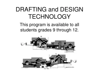
Civil Drafting Technology Chapter 2 Computer-Aided Design and Drafting (CADD)
Figure 2–1: Model files contain the individual elements that make up the final drawing, such as the property lines, buildings, utilities, dimensions, and various drawing features on their own layers.
Figure 2–2: A sheet file brings the model files together to create the composite drawing, and it includes the border and title block.
Figure 2–4: A variety of line types are included in the U.S. National CAD Standard.
Figure 2–5: The text fonts recommended by the standard are the basic monotext font and a variety of forms of the Romans font.
Figure 2–6: a) Standard drawing sheet sizes (ASME Y 14.1). b) Standard metric drawing sheet sizes (ASME Y 14.1M).
Figure 2–7: A simplifies pictorial representation of a CADD layering system, showing how information is shared among drawing components. Typically, each group of items is drawn on its own layer.
Figure 2–8: The location of the insertion points on mapping symbols.
Figure 2–9: When you enter sheet layout, a real-size sheet of paper is placed over the top of the model drawing. Border line, title blocks, and notes are also found on the real-size paper layout. The model drawings and the layout sheet are put together for plotting.
Figure 2–11: Exercises that can help reduce workstation-related problems. You should consult with your doctor for further advice and recommendations before using any of these practices.