Download
1 / 34
340 likes | 557 Views
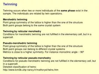
Corrections and Twinning. Absorption Correction Extinction Correction Determination of Absolute Configuration Twinning. Absorption.

E N D
Corrections and Twinning • Absorption Correction • Extinction Correction • Determination of Absolute Configuration • Twinning
Absorption • Since the diffractometer has 4 circles and there are three dimensions there must be many ways to bring the crystal into the diffracting position—that is so it obeys Bragg's Law. • If the crystal is not spherical than the orientation of the crystal will effect the intensity because of absorption. • There are two beams to be considered • The entering (incident) beam • The scattered beam.
What are the Symptoms of Absorption? • Badly shaped atoms that all point in the same direction • Lots of ghosts (electron density close to atoms that is not real). • Non-positive definite atoms.
INPUT: absorption coefficient μ, crystal radius, data with θ angle OUTPUT: transmission factors for each datum ADVANTAGES: exact calculation DISADVANTAGES: few spherical crystal samples Spherical Correction
Analytical Correction INPUT: absorption coefficient μ, data with direction cosines, description of the crystal by bounding faces OUTPUT: transmission factors for each datum ADVANTAGES: exact calculation DISADVANTAGES: crystal must have well defined faces
INPUT: data with direction cosines or Eulerian angles, equivalent reflection intensities OUTPUT: relative corrections ADVANTAGES: no crystal description required DISADVANTAGES: much cruder than previous methods; may correct for systematic errors Semi-Empirical Corrections
All Hell Breaks Out Before using DIFABS, it is suggested that you read the following journal article: Nigel Walker and David Stuart, "An Empirical Method for Correcting Diffractometer Data for Absorption Effects", Acta Cryst. (1983), A39, 158-166. DIFABS has received a large amount of bad verbage as a practical method ("DIFABS is EVIL!"). How much of this is based in reality, paranoia, philosophy, etc is still up for discussion(?). It is possible for DIFABS to be used to soak up sloppy practises in diffractometer setup and crystal alignment (non-full irradiation of the crystal), etc, etc, etc.
A web page to refer to is "Should DIFABS be Banned?": http://www.unige.ch/crystal/stxnews/stx/discuss/dis-dif2 Within the limitations described in the original DIFABS paper above, it does seem(?) to be a method worth keeping in your crystallographic bag of tricks to get the job done under some circumstances. http://www.ccp14.ac.uk/tutorial/wingx/absorp/difabs.htm
How Do We Handle Absorption • After integrating the data, frame scaling is performed. • For DENZO the program SCALEPACK is used • For EVAL the programs SADABS or TWINABS • Frame scaling makes sure that any loss of intensity from frame to frame is corrected for. • This automatically corrects for absorption • Can save data with direction cosines for use in other correction programs.
Extinction • For very intense reflections in high quality crystals it is possible that the diffracted beam can be further scattered by other unit cells. • This is called extinction and results in the very intense reflections being weaker than expected. • It can be corrected for in SHELX by adding an EXTI card or using the refine gui to insert one. • The SHELX output will indicate when an extinction correction is required. • Note this should be done after OUTLIER.
Absolute Configuration • It is possible to determine the absolute configuration of a molecule using crystallographic data. • There are two cases that must be considered • The space group is polar and the molecule is enantiomorphic. • There can be no mirrors, glide planes, inversion, or improper rotation axes. • Such space groups contain no letters or bars in the symbols after the centering type.
Absolute Configuration • The unit cell is accentric and enantiomorphic but the individual contents are not. • Polar space groups—P21, P212121, P61 • Accentric non-polar space groups – Pna21, I41/a • For both cases the absolute configuration of the unit cell must be determined even if the contents are racemic! • Absolute structure determination involves anomalous scattering.
Source of Anomalous Scattering • The normal scattering of the x-ray beam is all in phase – 180° off of the incident beam. • It is possible to have absorption, followed by emission. These photons will have a different phase from the normally scattered beam depending on the lifetime of the virtual state. • These are the anomalous photons. • Since there is an equal probability for emission in any direction, the intensity is NOT a function of θ.
Representation of Anomalous Photons • One way to represent a wave is by using an imaginary number. • The real part represents the intensity in the phase unsifted wave. • The imaginary part represents the phase shift. • Anomalous scattering is given as f' and f” where f' is the real part and f” is the imaginary part.
Crystal Symmetry and Anomalous Scattering. • Centric Space Groups. • In this case the imaginary part of the anomalous scattering must cancel out and become zero. • This is because by symmetry + and – must be identical • Friedel's law (Ihkl = I-h-k-l) is fully obeyed • Accentric crystals • The imaginary part will either add or subtract to the regular scattering. • When the absolute configuration is correct the sign will be correct otherwise it will be reversed.
Some Comments • To observe anomalous scattering there must be some absorption. • In general first row elements do NOT absorb enough of a Mo beam to provide data. Use copper. • Because the anomalous scattering does not fall off with theta but the normal scattering does, the high angle reflections will have the biggest changes when anomalous scattering is included.
How to Determine Absolute Structure • Johannes Martin Bijvoet at the University of Utrecht was the first to realize this could be done. • His method • Collect all data including Friedel Pairs • Solve and fully refine the structure. • Change the enantiomer and re-refine • Look for data where the Friedel pairs differ greatly in one of the two refinements • The refinement with the lower differences is the correct one.
The Bijvoet Method • Problems with it • Requires twice as much data • Requires a good deal of manual work • Provides no quantitative measure of the correctness • Fairly slow
R-factor Comparison • Refine both enantiomers. • Look at the r-factors. • Use the Hamilton t-test to determine if any difference is statistically meaningful and to what degree. • Rarely done anymore.
Refinement Methods • The idea is to add a parameter to determine the correctness of the configuration. • Rogers suggested using a multiplier to the sign of the imaginary part of the scattering factor. • If refined to +1 then correct, -1 incorrect. • This parameter does not converge well in least squares calculations so does not work well • Howard Flack suggested that both enantiomers be refined together. • The one given would be given a multiplier of (1-x) while the other one would be x
Flack Parameter • Thus if the Flack Parameter (x) refines to zero than the enantiomer is correct, while 1 is incorrect. • The Flack Parameter can take on values outside of 0 to 1. These are generally meaningless and suggest the anomalous scattering is too weak to provide the answer. • The s.u. in the Flack Parameter is important. • 0.2(1) suggests correct. • 0.2 (6) suggests nothing.
Flack Parameter • Advantages • Do not need Friedel pairs to calculate. • Provides a quantitative indicator of the absolute configuration. • Disadvantages • The Flack Parameter tends to correlate with other parameters when there is not much Friedel pair data. • It is not Chemist friendly
The Hooft Approach • Rob Hooft and Ton Spek worked on a new approach which was recently published. • They assumed that most of the Friedel data would be collected which is true for modern area detectors. • Their method is in PLATON as Bijvoet calculation.
Hooft Method • Advantages • Very Quantitative • Chemist Friendly • Lower errors on the Hooft y Parameter than the Flack Parameter • Disadvantages • Requires Friedel pair data • Is very sensitive to how data is collected.